From CNC machines to bicycle trainers, rotating machinery is all around us. As design engineers, we’re constantly trying to control things that rotate - brushless motors and ballscrews just to name a couple. One of the fundamental enablers of precision motion control is the ability to measure angular velocity (speed and direction!). Quadrature encoders are an essential tool in the toolkit of anyone doing robotics, automotion, or controls design specifically because they enable precise measurement of angular velocity, and by extension angular position and acceleration. In this article we’ll be diving into the design of quadrature encoders, the sensor technologies they utilize, common applications, and how to think about encoder selection on your projects. As always we’ll be going deep into first principles so you can apply these learnings across all domains and design scenarios.
Fundamentals of quadrature encoders
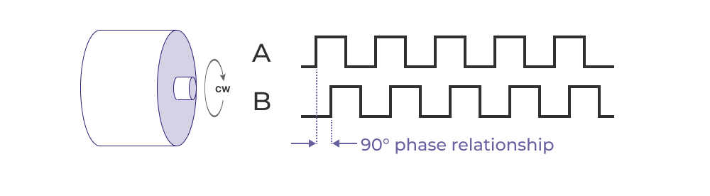
A quadrature encoder is a specific type of incremental encoder that uses two measurement channels (A and B) to detect the relative change in position of a rotating body, as well as the direction of rotation (clockwise vs counterclockwise).
You may be wondering, if there are two channels, why the heck are they called quadrature?
This name comes from the electrical phase relationship between the two channels. The two channels produce a pulse train that is 90 degrees out of phase. This phase difference allows the encoder to provide not only position and speed information but also the direction of rotation. It’s easiest to understand this by visualizing the idealized output from a quadrature encoder with digital optical sensors.
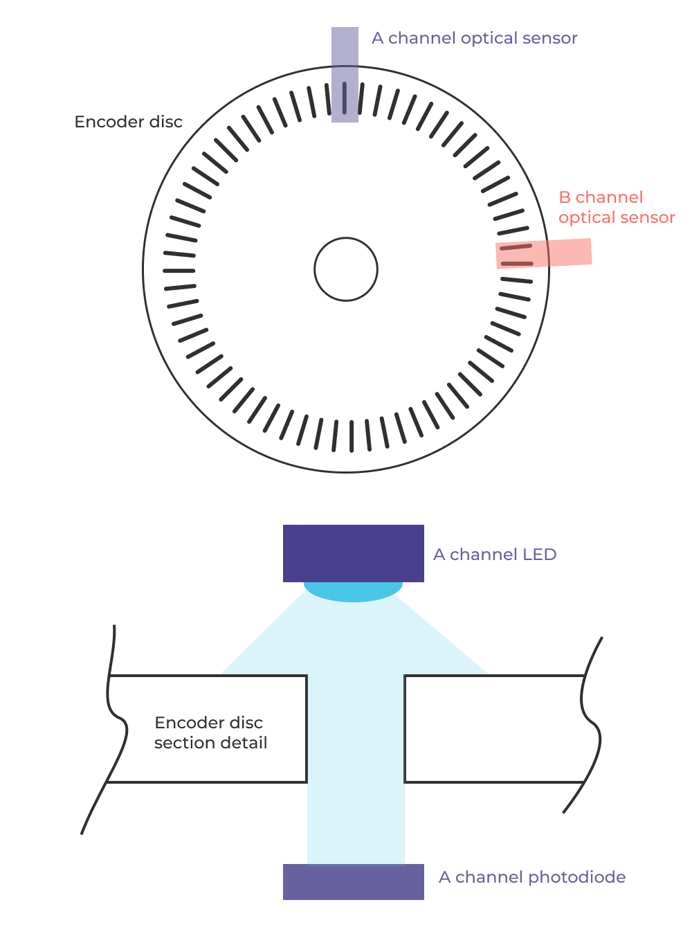
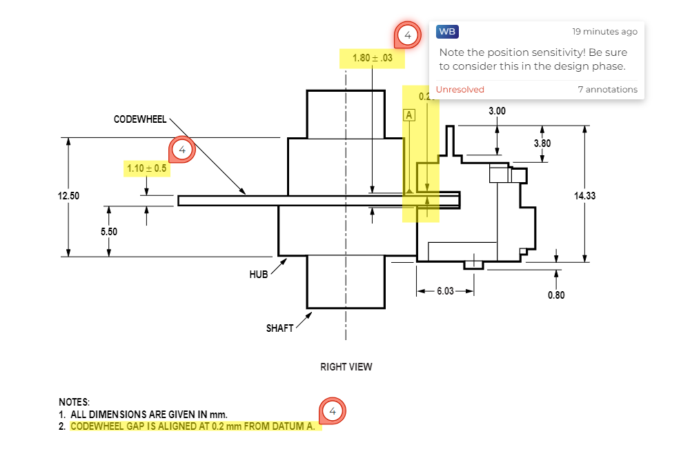
The basic working principle involves a rotating disk with alternating opaque and transparent sections. As the disk rotates, a light source and a photodetector on either side of the disk generate electrical signals as the light is alternately blocked and passed through the disk's sections. These signals form the basis of the quadrature output.
Design considerations
In many products, you may end up implementing an encoder from scratch. This will require you to design an encoder disc, position your sensors, sample them at an appropriate frequency, and then interpret the data to determine changes in position. Let’s walk through how to do that and what to consider.
The first thing to think through is the position accuracy requirement for the application. Then consider the range of velocities and accelerations you are trying to measure and what sampling frequency will give you the desired performance. This can actually be a tricky question if you are doing closed loop control and your desired control behavior includes an output that is proportional to rotational acceleration (for example, low jerk precision motion control applications).
Position
Position requirements are the easiest to determine. If you have a ballscrew that moves 10mm every rotation and you want 0.1mm positioning control, you need to be dividing each rotation into 100 measurable positions. This dictates how many divisions you have on your encoder (and thus the implied resolution). In this example we can get 100 measurable positions with 25 pulses per revolution. Remember that two sensors in a 90° phase relationship can measure 4 positions per pulse on each individual channel.
Velocity and acceleration
Next you’ll need to think through what velocities and accelerations you want to measure for your controls/sensing application. Then think back to your instrumentation class and remember the concept of Nyquist frequencies. You’ll want to make sure you sample your sensors such that you detect all state changes in disc position at the velocity you care about. Because quadrature encoders are incremental, missing a pulse or two can cause very large irrecoverable errors.
Continuing with our example above, lets say we want our ballscrew system to have a max linear velocity of 100mm/sec. This implies a max angular velocity of 10 revolutions per second, or 20π radians per second. Since we have 25 pulses per revolution this means we need to measure 250 pulses per second. In order to guarantee that we don’t miss a pulse, we’d want a sampling frequency of 500Hz or better. There’s a bit more to this process when you start looking at acceleration measurement, but this should get you in the right headspace to understand how encoder resolution and sampling frequency are related.
Making sense of direction by reading state changes
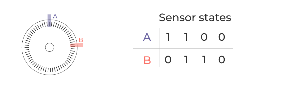
Ok so now that we have a sense for the basic architecture and electromechanical design of quadrature encoders, let’s try to make sense of their output. We have two channels (A & B) and each sensor can have two states (high or low). This gives us 4 possible states for the encoder, mapped out below.
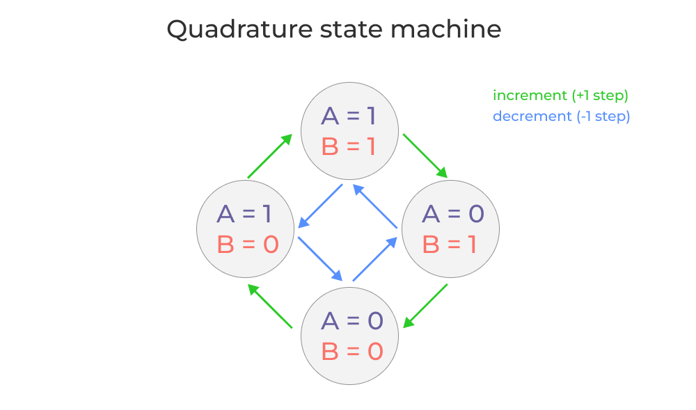
Direction can be determined by detecting changes in the state of each channel and applying some conditional logic.
For example, let’s start by assuming A = 1 and B = 1 and we are starting at a rotational position of zero degrees. If the A channel changes to 0, then the encoder increments one step. If instead the B channel changes to 0, the encoder decrements one step. In this way you can think of the encoder as a state machine that just adds a fixed value (equal to the resolution) to a running counter based on what state transition is detected.
The challenge electromechanically is to ensure that you can reliably read those state changes and recover from any errors (for example, if you switch from A=1, B=0 to A=0, B=1 because a step is missed).
Overview of sensor technologies used in quadrature encoders
In principle you can build a quadrature encoder with any sensor technology as long as the transducer changes state as a function of disc rotation. In practice, most quadrature encoders use one of three sensor technologies; optical, magnetic, and capacitive sensors.
- Optical Encoders: Optical encoders are the most common type of quadrature encoders. They use an LED light source and a photodetector array to detect the passage of light through the encoder disk. The precision of optical encoders makes them suitable for applications requiring high accuracy.
- Magnetic Encoders: Magnetic encoders use magnetic fields to detect the rotation of a disk (usually via hall effect sensors). A magnetized disk rotates in front of a sensor, which detects changes in the magnetic field. These encoders are more robust than optical encoders and can operate in harsh environments with dust, dirt, or oil.
- Capacitive Encoders: Capacitive encoders detect changes in capacitance as a disk rotates. They are less common than optical and magnetic encoders but offer advantages in terms of immunity to environmental contaminants and potential for miniaturization.
Example datasheets with comments
I went ahead and found some example encoders, downloaded the datasheets and uploaded them to Five Flute with a few comments on applications and design considerations. You can check them out via the links below.
Example magnetic encoder datasheet.
Example optical encoder datasheet.
Applications of Quadrature Encoders
Quadrature encoders are used in a wide range of applications where precise motion control is required. Some common applications include:
- Robotics: In robotics, quadrature encoders provide essential feedback for motor control, allowing robots to move accurately and precisely. You can mount them directly on stepper motors to build your own servos for example.
- CNC Machines: CNC (Computer Numerical Control) machines rely on quadrature encoders for precise positioning of the cutting tools.
- Industrial Automation: In automated production lines, quadrature encoders are used to monitor the position and speed of conveyors, robotic arms, and other machinery.
- Motor Control: Quadrature encoders are critical in servo motors and other motor control systems, providing feedback to ensure accurate speed and position control. Especially in brushless motor commutation applications, accurate position sensing is essential for motor performance.
Writing code to read quadrature encoders - Arduino example
Reading the signals from a quadrature encoder involves detecting the transitions of Channel A and Channel B and interpreting them to determine the position and direction of rotation. Below is an example of how to read a quadrature encoder using an Arduino microcontroller.
// Define the pins for Channel A and Channel B
const int pinA = 2;
const int pinB = 3;

// Variables to store the current and previous states of Channel A
volatile int lastAState = LOW;
volatile int currentAState;
volatile int position = 0;

void setup() {
  // Initialize the serial communication
  Serial.begin(9600);

  // Set the encoder pins as inputs
  pinMode(pinA, INPUT);
  pinMode(pinB, INPUT);

  // Attach interrupts to the encoder pins
  attachInterrupt(digitalPinToInterrupt(pinA), readEncoder, CHANGE);
}

void loop() {
  // Print the current position to the serial monitor
  Serial.println(position);
  delay(100);
}

void readEncoder() {
  // Read the current state of Channel A
  currentAState = digitalRead(pinA);

  // Determine the direction of rotation
  if (currentAState != lastAState) {
    if (digitalRead(pinB) != currentAState) {
      position++;
    } else {
      position--;
    }
    lastAState = currentAState;
  }
}
In this example, the Arduino reads the states of Channel A and Channel B and increments or decrements the position variable based on the direction of rotation. The attachInterrupt function is used to call the readEncoder function whenever there is a change in the state of Channel A, allowing for real-time position tracking.
Final thoughts
I’ve been involved in a surpisingly large amount of projects where position sensing with encoders played a crucial role in the product performance. Most of the time I had electrical engineering support, but having the ability to use a data acquisition system and read encoder values on my own always helped me be more efficient. I hope this article has given you a foundation to do the same on your projects. If you are interested in more about motion control for machine design, please email our team at support@fiveflute.com and let us know!
Cheers!
Related content
How to design waterproof products
Bearings and bushing - essential components for mechanical engineers