Project Electra - How to adapt a new electric drivetrain to a 1950’s transmission - Part II of II.

Welcome (back) to ‘Project Electra’
Hi Enginerds, we’re back with the next update on Project Electra, our 1958 Mercedes-Benz 220S EV conversion build with Dave Evans from Fictiv.
If you haven’t caught up with the latest on the project you might want to check out this launch article on engineering.com as well as our first post on the Five Flute engineering articles page. In this article we’ll be continuing on with the mechanical design needed to adapt the 1950’s transmission to our HyPer9 high voltage motor as a replacement for the existing internal combustion engine.
So far we have a motor coupler and motor mount designed, and a top level assembly that we’re building in OnShape using Polyscan 3D point cloud data of the engine bay. Right now we don’t yet have a trustworthy position for the transmission in our top level assembly, so much of the design will be conceptual sketch based and then built in place. This project has been a great chance for Dave and I to step outside the neat and tidy world of CAD and get back to a mindset of just making things work, like most garage/home shop builders!
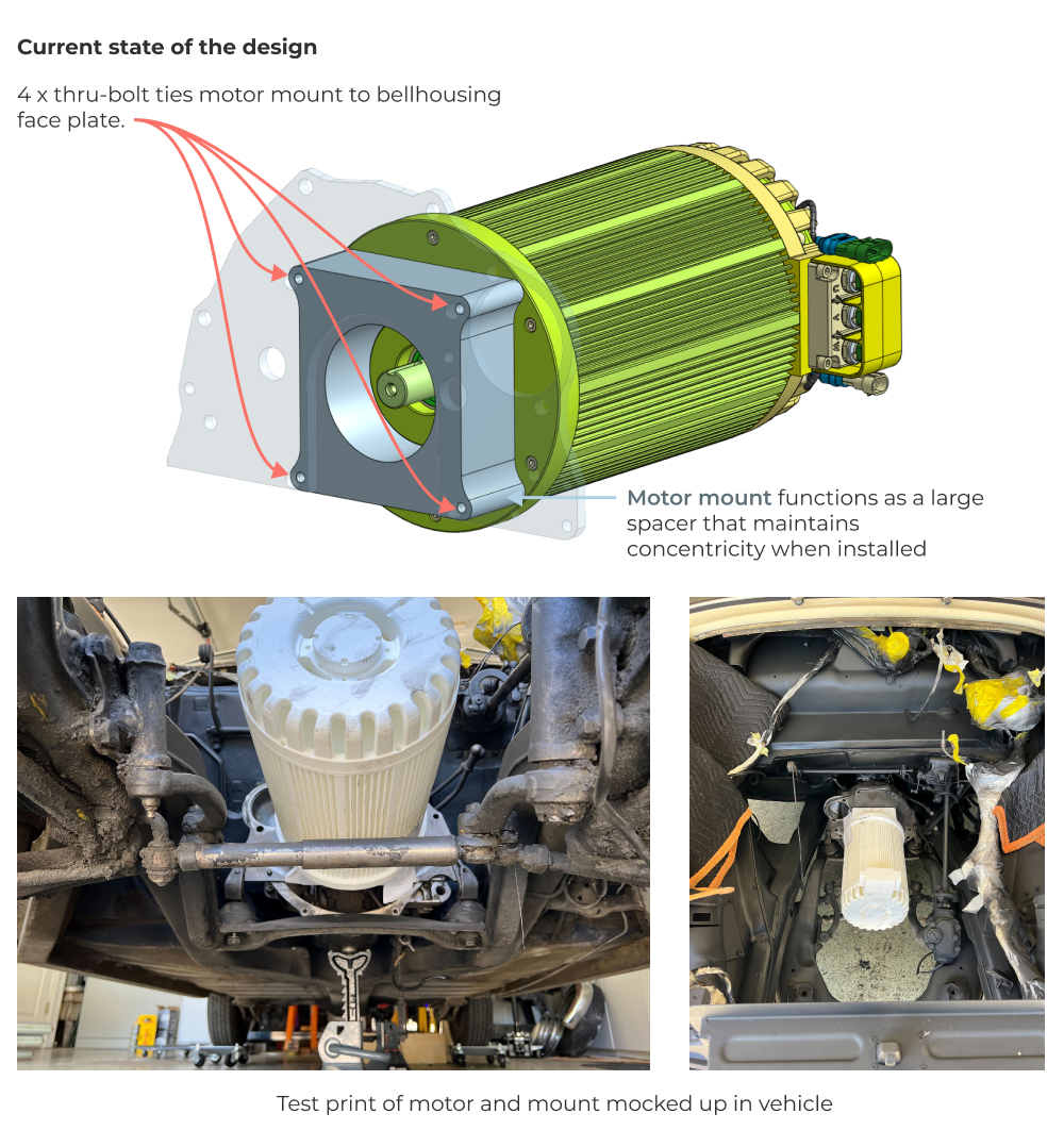
This article will be primarily focused on mounting the drivetrain assembly securely relative to the chassis, but we'll also give a quick update on manufacturing progress as well. The current state of the drivetrian design is shown below.
Manufacturing progress
Motor mounting
We kicked off the manufacturing of our motor coupler and motor mount. It definitely helps to have machine shop access thanks to the Fictiv team. One of the coolest parts of this manufacturing effort was mounting the entire tranmission and bulkhead assembly into the CNC in order to locate the drive axle centerline accurately. Here’s a quick look at the CNC setup.
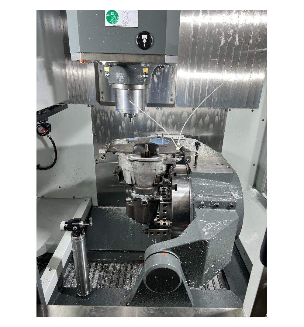
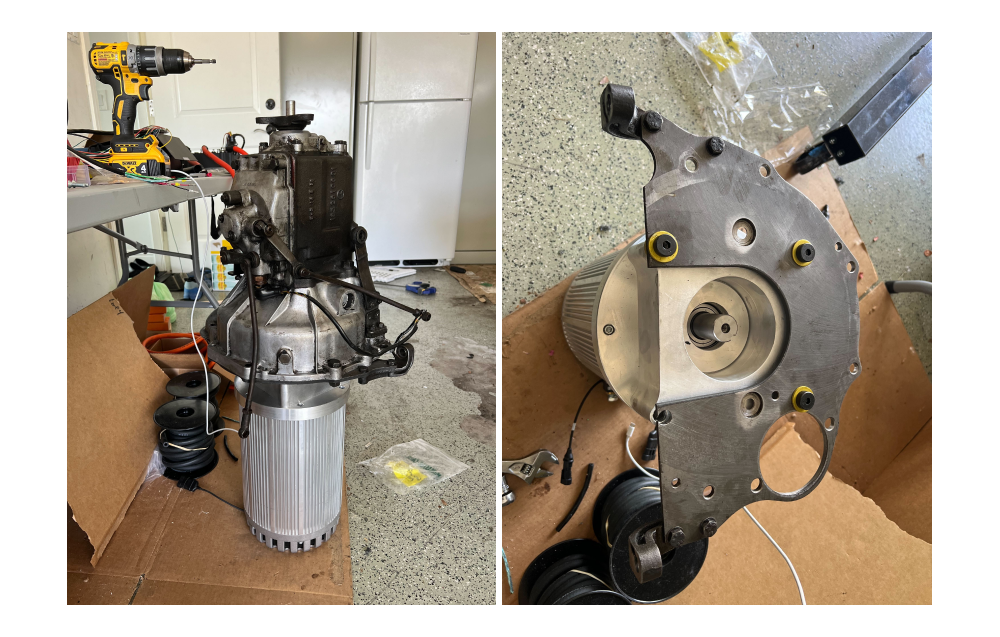
This setup was used to locate the 4 motor mount holes in the bulkhead relative to the transmission. Here’s the completed subassembly.
Motor coupler machining
One of the more challenging aspects of manufacturing overseas is the lack of visibility into the machining process. For better or worse, many Chinese and Taiwanese machine shops have a “whatever it takes” attitude toward part production. This means they are incredible resourceful and will generally get the job done not matter the cost (and I don’t mean strictly financial cost). It’s important to understand this if you are someone specifying parts. The motor coupler design on project electra is a great lesson in how manufacturing processes can impact part performance.
The motor coupler was designed with a fairly tight toleranced spline profile that interfaces with the transmission output shaft. You can check out the full detailed drawing here.
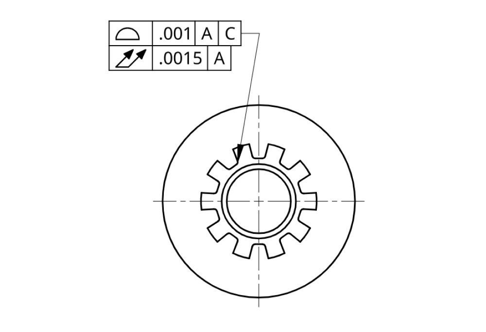
During design we’d imagined that the profile would be cut either using a CNC broach or sinker EDM. The manufacturer ended up using the EDM approach, but what was most surprising was the method for fixturing the part. During machining, they ended up welding a piece of square stock to the OD of the partially finished coupler. This allowed them to clamp the part in a vise, which easily allowed them to register the part relative to EDM tools. This enabled them to position the keyway slot relative to the spline simply by flipping the part in the vise. What’s interesting is we don’t even need the keyway to be aligned relative to the spline! However, the way that I made the drawing and used a profile feature control implies that this alignment is critical, and the manufacturer took this at face value! I never would have imagined they’d solve this feature alignment problem by welding and post machining. Wild!
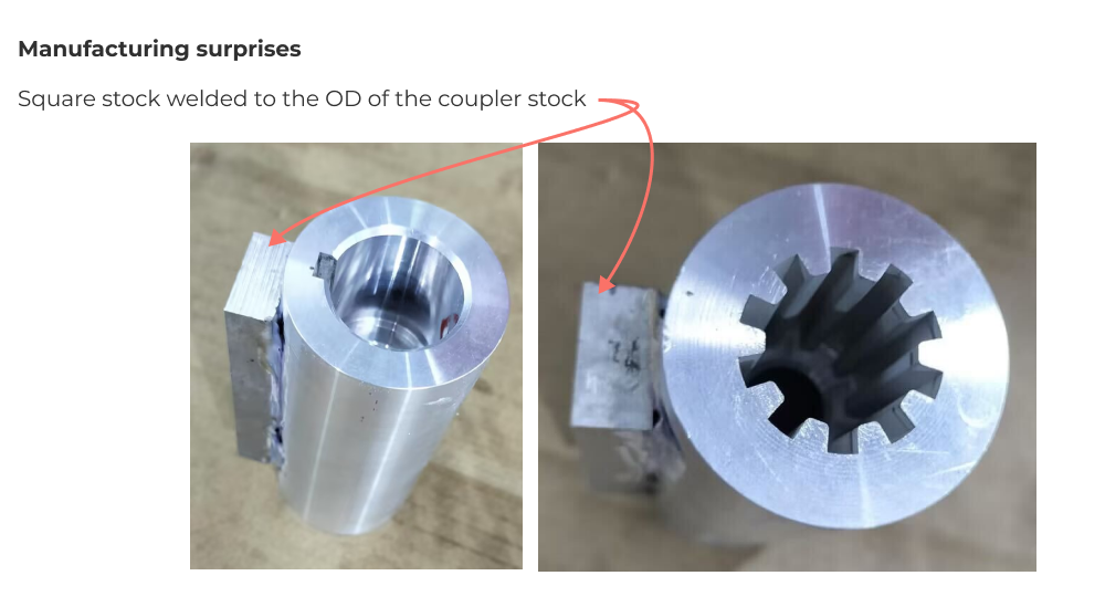
After sinker EDM cutting the spine and keyway, they turned down the OD of the part to get rid of the square stock. Who knows how deep the welding heat affected zone penetrated the part and what impact this may have on the strength of the part!
This is the exact type of manufacturing surprise that can sink a production project by compromising part strength. The lesson here is you don’t know anything about how your parts are made unless you see it for yourself!
Existing transmission mounts and engine mounts
Alright, moving on to the current design challenge, let's review the mounting problem at hand. The transmission mounts directly to the rear chassis mounts, which we are retaining in our design.
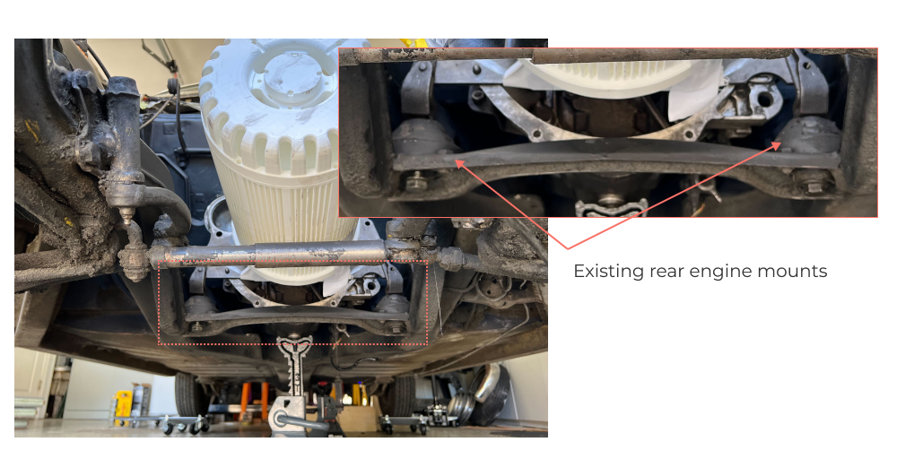
With only two rubber bushing style mounts, the entire motor and transmission subassembly can pivot about the line between these mounts. So the current design challenge is to figure out how to constrain the system now that we don’t have an internal combustion engine attached to the forward engine mounts on the chassis. We also want to do this in such a way that we’re stressing the chassis in a similar manner to the OEM design.
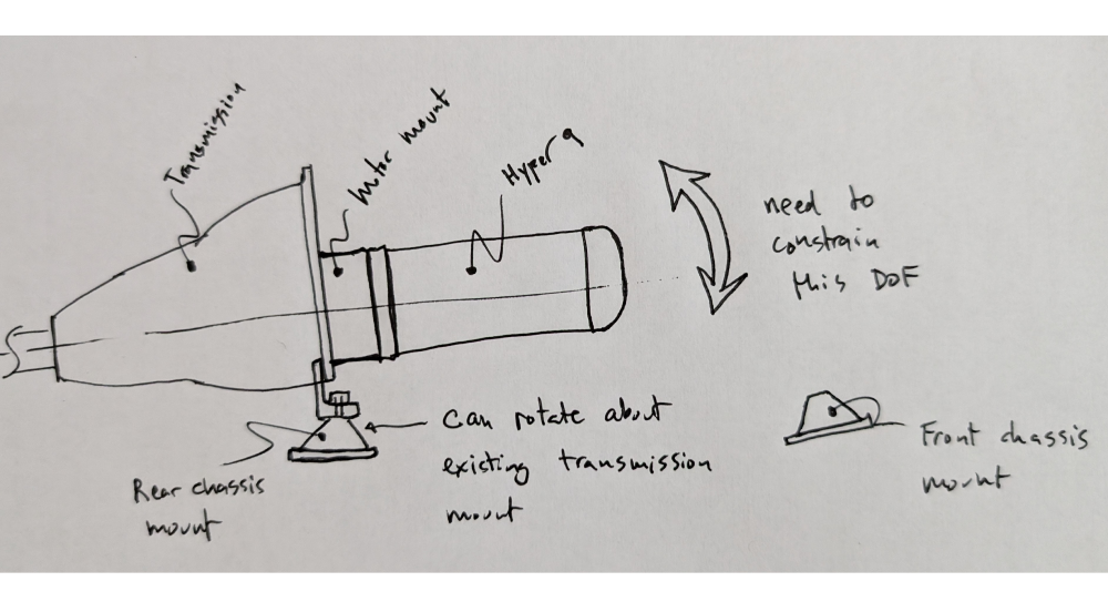
Transmission and motor mount concept design
After a round of concept designs internally, we settled on a very prototyping friendly design that uses an 80/20 extruded aluminum frame built directly into the transmission bulkhead. This frame extends over the Hyper 9 motor and down to the chassis. A pair of rubber bumper style mounts will be attached directly to the chassis rails (the OEM mounts are similarly threaded directly into the weldment). The 80/20 frame will connect to these bushings via spherical rod end bearings threaded into the frame.
Here’s a quick set of concept sketches that we threw together after we settled on the design.
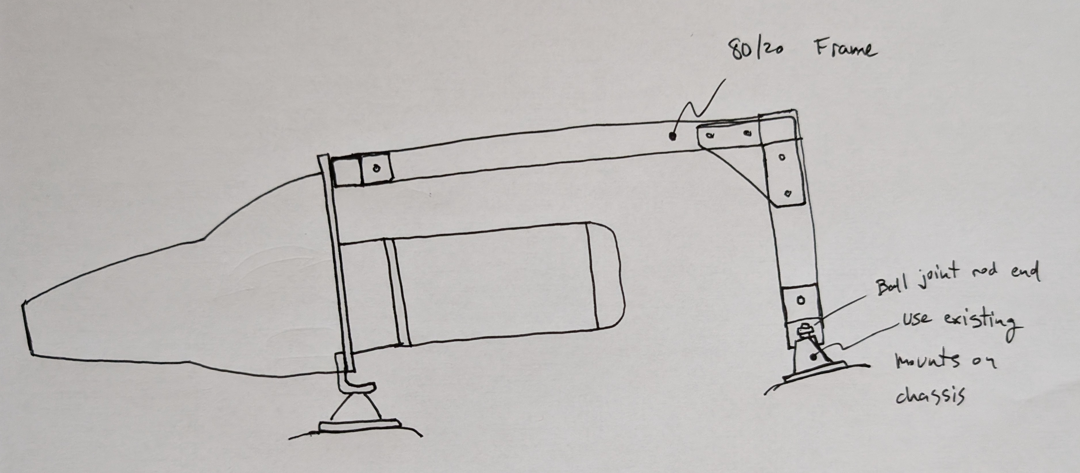
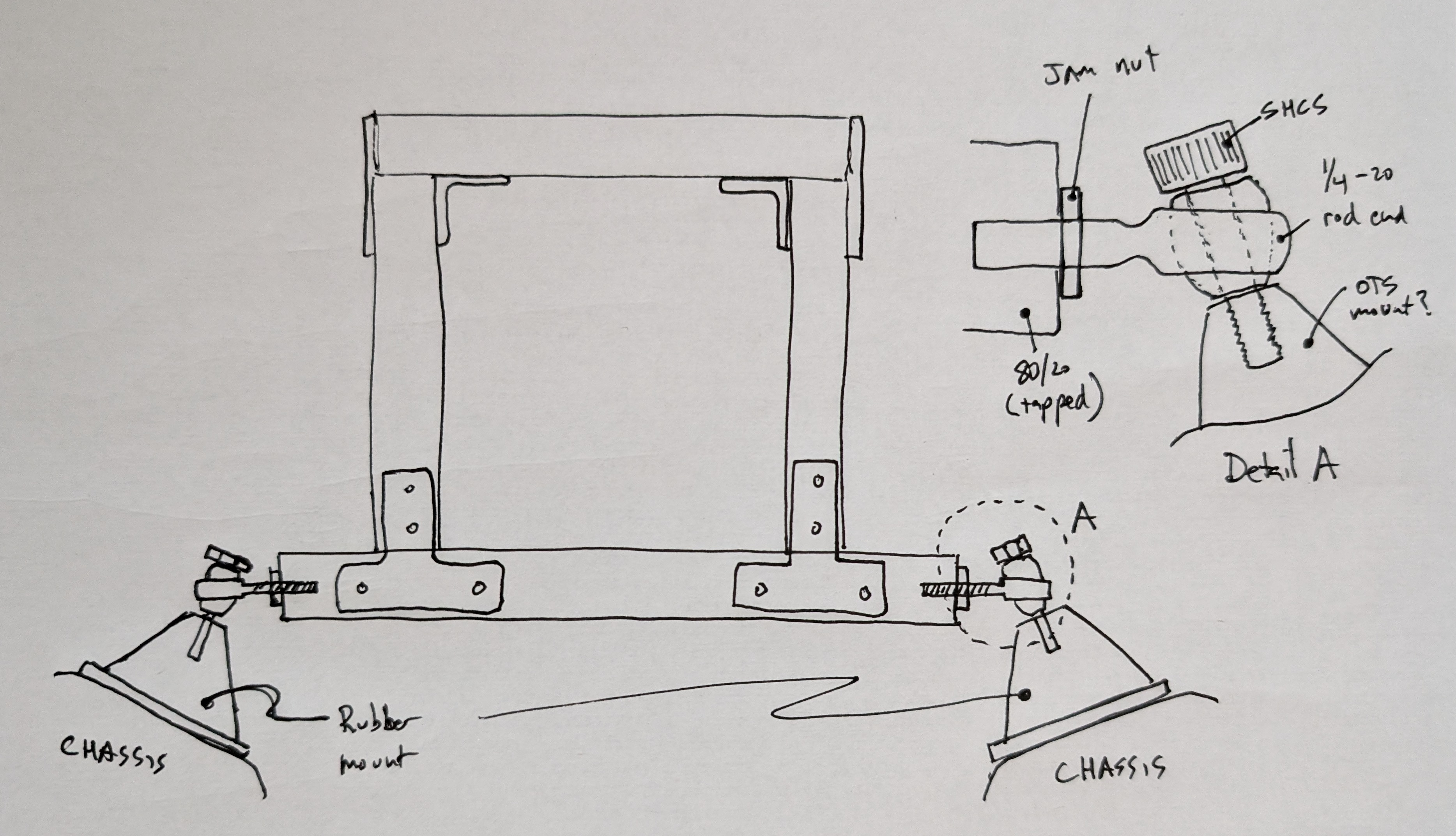
Now I know you are probably judging this design already so I wanted to lay out our thinking. I’m fully aware that we’re commiting the cardinal sin of putting threaded rod ends in bending. Yes it’s a fatigue nightmare. But its easy to build! We’re just trying to prove out a concept with this design and use it for initial vehicle integration and bringup. At some point we’ll swap out to a sheet metal design that is mechanically more robust. For now, the 80/20 approach allows us to build the frame to fit, which is a huge advantage given that we don’t have a top level model that is accurate enough to design for in detail.
Back of the envelope hand calcs
In terms of working loads on the transmission mounting frame, the worst case loading condition is inertial. We’re assuming a 5G bump condition (shout out to my FSAE colleagues) and an extremely conservative center of gravity location relative to the existing engine mounts. Doing a quick moment balance around the engine mount gives us a ballpark reaction force provided by the frame for out worst case 5G bump loading condition.
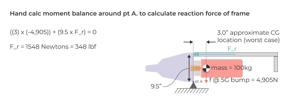
This puts approximately 175 lbf on each rod end under a ridiculously conservative worst case scenario. For this project, we feel like this is a risk worth taking in the interim before we have a more polished sheet metal design.
Wrapping up and next steps
That’s it for this update on Project Electra! We’ve been making slow but steady progress on design and now the build tasks are piling up. Next up we’ll start the battery box design and feature an update into the transmission mount build. Ideally we’ll have some good build photos to show off as well as some progress with an electronics roadkill prototype that Dave is using to bringup the motor and drivetrain electronics. We’ll also be doing a live event where we talk through the design and build process with Dave Evans from Fictiv.