Before we begin
Hey product developers and engineers! If you get parts made you've probably run into manufacturing issues. Sometimes the part you receive doesn't function like you drew it up in CAD. Tackling manufacturing issues can get complicated, so we've built Five Flute to help you keep it all sorted. Teams that use Five Flute discover and resolve more issues with their prototypes, delivering better products in less time. If you want to tackle manufacturing issues and collaborate with your engineering team more efficiently check out Five Flute today or sign up for a demo!
Intro
Mechanical Engineers and Industrial Designers should have a basic understanding of milling tools used to make the features and parts they design. Understanding the different types of tools and their usage allows designers and engineers to infer the cost and complexity of their design decisions. In this article, we're going to review commonly used tools in a CNC Vertical Milling Center (VMC) along with brief descriptions of how they are used. The goal is to better equip design engineers and hardware product developers to answer the following questions:
- What tools are ubiquitous in all machine shops?
- What kinds of features do different tools commonly make, and why?
- By extension, what features are “cheap”?
Face mill
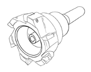
A face mill is often the first tool used to create a part. Face mills typically have multiple indexable inserts attached to a modular “shell” which is then bolted to a tool holder/arbor. Sometimes called shell mills, these tools are used primarily for bulk stock material removal such as facing (sometimes called decking). Face mills allow machinists to use all of the spindle horsepower at their disposal to remove material as fast as possible.
Square end mill
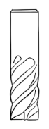
The ubiquitous square end mill is the jack-of-all-trades and a workhorse tool in most milling centers. It comes in diameter ranges from 0.010” to around 2”. Square end mills cut with the face and sides of the tool allowing machinists to create pockets and contours entirely with one tool. Tool geometries vary depending on application, but the vast majority of square end mills have 2 or more flutes with a helical geometry. Tool geometry itself depends so much on materials and applications that we will be created a dedicated post just to talk through it (coming soon...).
Bullnose end mill
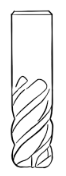
The bullnose end mill is like a square end mill but with rounded corners. Bullnose cutters allow face and side milling operations while leaving a blend radius at the intersection between the two. Some machinists prefer bullnose end mills for roughing operations because the end mill corners are less likely to accumulate heat or chip damage during roughing.
Ball end mill
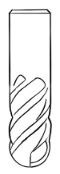
A ball end mill is like a bullnose end mill where the corner radius is equal to the tool radius. Ball end mills are often used for surfacing, 3D contour operations, or for interpolation of chamfer features (particularly on 5 axis parts). The primary downside of ball end mills is that the effective cutting speed (SFM) varies largely as a function of radius. When creating fillet features with radii equal to the tool radii the center of the tool is moving at effectively zero velocity. This can cause variance in surface finish, or cause the machining operation to be slow in order to compensate for the decrease in tangential velocity of cutting faces near the tool center-line. The following video shows a large ball end mill being used for a semi-roughing 3-D machining operation. Note the use of the 5th axis to incline the head of the milling machine, allowing the tool to make contact with the work piece away from the tool centerline.
Chamfer mill
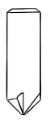
A chamfer mill is an end mill designed to cut chamfer features. Chamfer mills are most often used for deburring (breaking machined edges), and occasionally used for countersinks. They commonly come in 30, 45, and 60 degree angles. If you design an uncommon chamfer angle into your parts, it’s likely the chamfer feature will be interpolated with a ball or bullnose end mill and may have a correspondingly poor surface finish as compared to a standard chamfer.
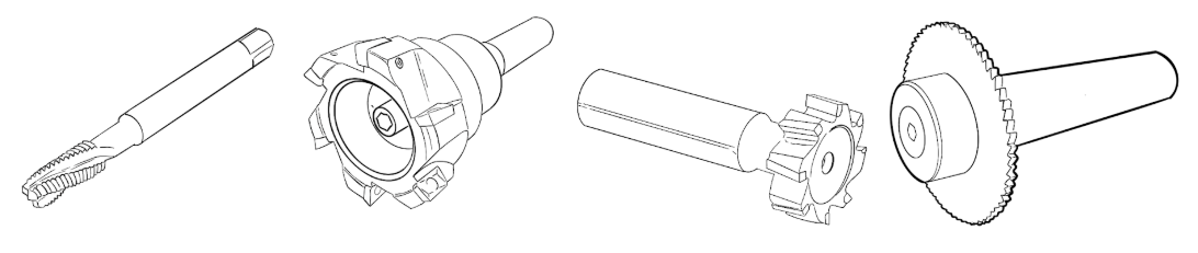
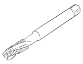
Taps
Taps cut threads into parts. Taps require either 1.) a tapping head or tool holder, or 2.) a machine that is capable of rigid tapping. Rigid tapping is the synchronization between the Z axis motion of the tool and the rotation of the spindle, such that taps can be retracted after threads are formed, without damaging the newly formed threads. High accuracy optical encoders combined with variable frequency drive spindle motors allow modern CNC controllers to rigid tap with relative ease.
There are two primary types of taps employed in CNC machines, cutting taps and form taps. Cutting taps create threads by removing material selectively, in the shape of the desired thread form.
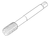
Form taps work by cold forming an undersized hole into a thread feature. Note that cutting taps and form taps have different pre-drill requirements! Form taps in certain materials can offer a stronger thread due to the cold work hardening at the thread root and crest.
This post by North American Tool gives a high level overview of the differences between form and cutting taps.
Keyseat cutters
Keyseat or Key cutters are used to create undercut features and t-slots. Often, the clever use of a key cutter can eliminate an extra setup in a CNC machine; saving time and increasing feature accuracy. This video from AB Tools shows a radius keyseat cutter creating undercut features in a 3 axis vertical milling center.
Slitting saw
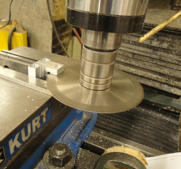
A slitting saw is essentially a specialty key cutter with a relatively large cutting radius, small width, and small arbor radius. This allows deep undercut slot features to be created. Many machinists use slitting saws to separate parts entirely, to cut deep groove features, or to make some jobs “single OP” where all features are created in one setup. Slitting saws are especially good at producing deep slot features in flexible parts, where a normal end mill would either require more machine time or induce chatter and poor surface finish.

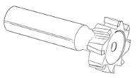
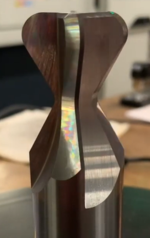
Form tools
Though not as common in prototyping, form tools are custom ground end mills that allow certain features to be cut at extremely low cost. Modern toolmakers are capable of grinding custom form tools for even low volume manufacturing operations. Form tools are especially useful in those instances where a part has rotational or mirror symmetry with sidewalls that would otherwise require interpolation or multi axis machining to create. Form tools allow machinists to avoid secondary operations or additional setups by enabling undercut geometry to be created in simple 3 axis VMC setups. If you want to learn more about form tools, follow Alfred from AB Tools on Instagram.
Custom o-ring groove dovetail tool created by AB Tools Inc.
Drills
Most job shops will have a large variety of drills on hand, covering wire size, letter gauge, fractional and metric drill diameters in both jobber and stubby lengths.
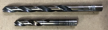
Jobber length (upper) vs Stub length (lower) drill bits
Renishaw Probe
Although not a cutting tool, the Renishaw OMP40 touch probe is one of the most useful tools in any prototype job shop. The OMP40 is a touch probe that allows CNC machines to effectively be converted to Coordinate Measuring Machines (CMM). Although not as accurate as a CMM, touch probes are used by machinists to locate and measure stock material, parts, part features, and fixtures inside the machine coordinate system. Probes are essential in providing accurate registration between features cut in different setups by allowing tight control of the work coordinate system relative to stock material.
This video from John Saunders at NYC CNC (Saunders Machine Works) shows the Renishaw probe locating the stock material in a Haas UMC-750 five axis milling machine.
Mapping Tools to Part Features
Now that we have a sense of what tools are commonly available at prototype machine shops, it can be helpful to look at a few machined part case studies to think through how these various tools are used.
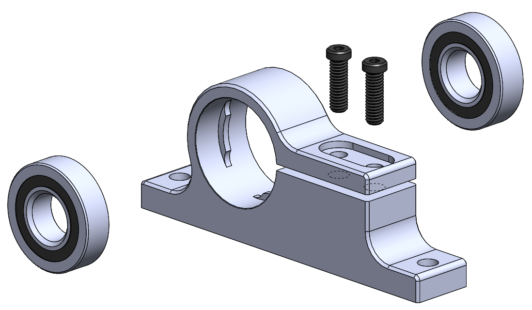
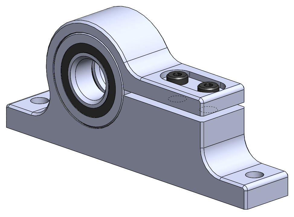
Clamping Pillow Block Example
This part holds two shielded roller bearings in a pillow block mount, with a flexible clamp that secures the two bearings by clamping on the outside bearing race of each bearing. The exploded and assembled configurations are shown below.
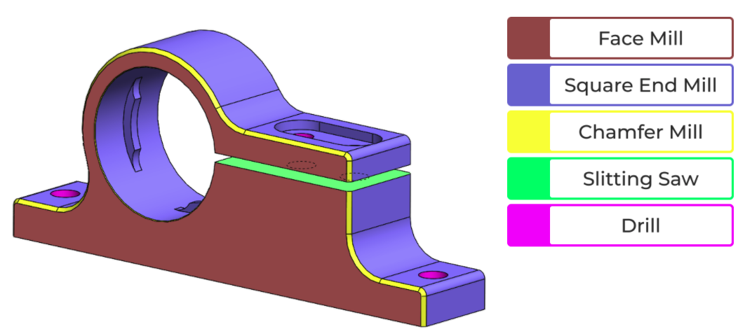
This color coded illustration shows the breakdown of tools used to machine the part on a per feature basis. Note the following:
- A square end mill does the bulk of the volume removal, profiling and finishing work
- The part requires at least three operations (likely four), where it is turned on its side in order to access the drilled holes and countersunk pocket for screw head clearance.
- The large cutout for the bearing clamp was made with a slitting saw, likely as the last operation on the part.
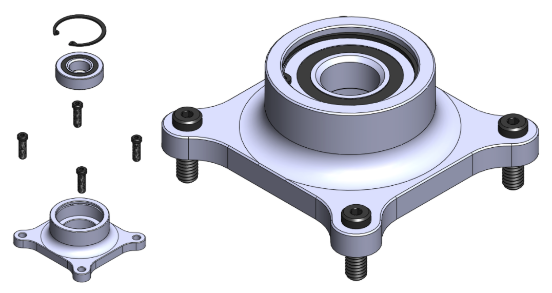
Snap-ring Bearing Block
Similarly, this part holds a shielded bearing in a flat pillow block mount, but with blind bore and snap ring for bearing retention. The exploded and assembled configurations are shown below.
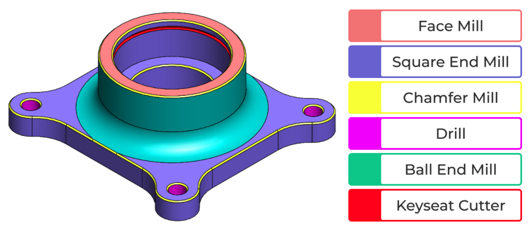
Again we use a color coded illustration to demonstrate the breakdown of tools used to machine the part on a per feature basis. Note the following:
- There is no other tool that can cut the snap ring feature. This kind of blind undercut feature can only be created with a keyseat cutter.
- The sides of the bearing housing will likely be finished by a ball end mill (or bullnose) in order to better blend the radius into the sidewall.
- With the right tools, this is only a two operation part as all features can be accessed from two opposing tool approach vectors. Despite the complexity of features, with the right tools this is a straightforward 3 axis machined part.
What Makes a Feature Cheap and How Does it Relate to Tools?
CNC part cost warrants a separate post due to its complexity, but from the standpoint of tools there are a few key takeaways worth knowing as a design engineer. The primary drivers of prototype part cost are NRE (programming time predominantly), setup time and machine time. A three minute reduction in cycle time can result in as much as a $10 reduction in part cost (assuming Bay Area shop rates for 5 axis milling). A "cheap" feature on a CNC machined part is one that is manufacturable with common tooling without requiring a special setup or special tool path.
As a design engineer, the features you design should balance functionality and manufacturability. Before releasing parts to machine shops, it can be very helpful to list the tools needed to make your parts and to estimate the number of setups in the CNC machine. Often a feature can be "refactored" to provide the exact same physical functionality, while requiring less effort to machine. Knowing the types of tools used in a job shop is essential to design engineers, but there is often no substitute for talking with a machinist directly. There may be machine or tool specific constraints that your machinists are operating under, that you can easily design around.
One more thing before you go!
Great product development is all about iterating quickly and learning as much as possible with each iteration. We've built Five Flute to help teams discover and resolve more issues per iteration so you can get to market faster and deliver products that meet your design requirements. If you want to supercharge your product development collaboration check out Five Flute today or sign up for a demo!