The Scotch Yoke mechanism is an efficient solution for transfering rotational motion into linear motion. In this article, we’ll be exploring the design of Scotch Yoke mechanisms in depth, so you can understand the basic principles at play and how to design Scotch Yoke mechanisms in the context of electromechanical assemblies. We’ll start with an overview of the mechanism, then an exploration of the governing equations of motion, followed by a discussion of practical applications in machine design.
The Scotch Yoke Mechanism Explained
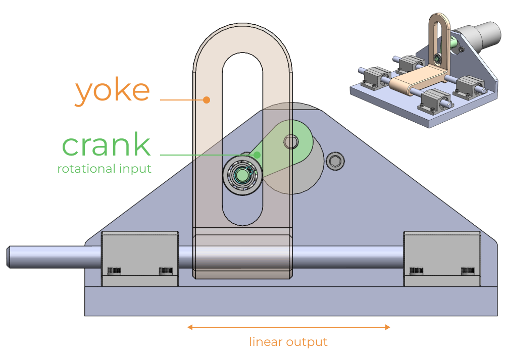
A Scotch Yoke mechanism is a unique type of motion converter. It consists of a pin (or crank), a yoke (a sliding block), and a guiding slot. As the pin moves in a circular path due to the rotation of a crank, it drives the yoke to move in a straight line. This simple yet elegant design is used in a variety of applications from power tools to combusion engines.
Detailed Design Considerations
Geometry and Motion Equations
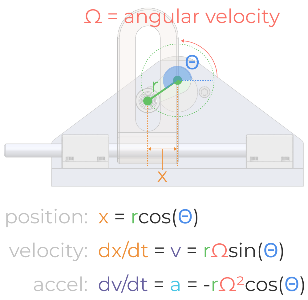
Fundamentally there are only a few input design variables in a Scotch Yoke mechanism:
- r: radius of the crank
- theta: angular position of the crank
- omega: angular velocity (ex: RPM of the driving motor)
From these input variables, the linear position, velocity, and acceleration of the sliding yoke can be calculated. In the diagram below, the equations for position, velocity, and acceleration are shown.
Design Worksheet and Example Model
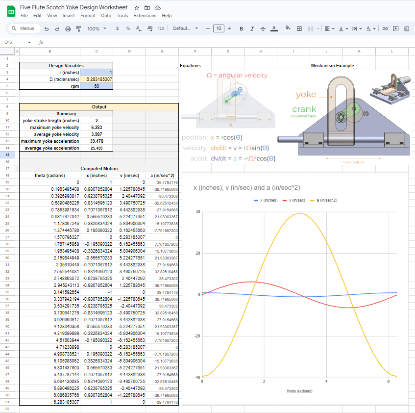
You can use the Five Flute Scotch Yoke Design Worksheet (excel template) to explore how the input design variables impact the motion of the mechanism. This is a great place to start when trying to determine the geometry of your components and how they relate to the dynamics of the yoke motion.
Check out this example mechanism model and this markup in Five Flute to download your free excel template for Scotch Yoke design.
Example use case - Jig saw design
Imagine you have been tasked with designing a jig saw for a major tool manufacturer. For simplicity and cost you’ve decided to use a Scotch Yoke mechanism to translate the rotational motion from a brushless DC motor to the reciprocating linear motion of the saw. How would you begin your design?
In this case we you can set the radius of the crank based off the desired saw stroke length. Then iterate the input angular velocity until you achieve the desired saw (linear) velocity. Neglecting the rotational inertia of the drive system, you can use the linear acceleration of the mechanism combined with the anticipated force required to cut material with the saw to get a an estimation of motor torque required. For this example lets set the desired stroke length to 2 inches and the input angular velocity of 60 RPM. The plot below shows the position, velocity, and acceleration of the saw (yoke).
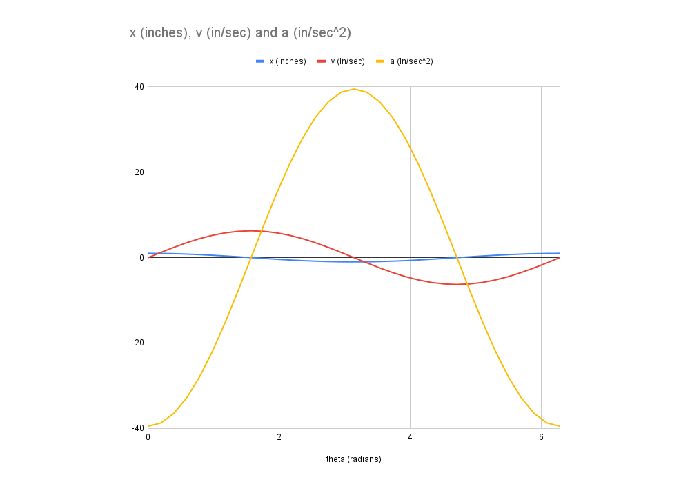
Note that there is a 90 degree (Pi/2) phase shift between position, velocity, and acceleration. From an intuitive perspective this makes sense as maximum velocity occurs at the zero crossing of position (in the middle mechanism position), and minimum velocity occurs at the end of stroke when acceleration is highest. Understanding the phase relationship between position, velocity, and acceleration of the yoke will build your intuition for component and motor sizing.
Other Design Considerations
Mechanically, the most critical interface of the Scotch Yoke mechanism is between the crank and the yoke. Some designs use a roller bearing (like the example mechanism in the beginning of this article), while other designs use a pinned slider or combined linear bearing with a bushing or ball bearing.
Whatever design you choose, be sure to consider the friction and and load conditions between the crank and the yoke, and design accordingly. For small, lightweight, low torque applications, a pin in a slot will suffice despite the line load bearing forces between the crank and yoke. For high impact or heavy duty applications, considerable care must be taken to manage the load distribution between crank and yoke in addition to consideration of inertial forces at play. In both cases you should consider managing friction and component wear with lubrication and service intervals.
For more information on bearing and bushing selection for Scotch Yoke and other mechanisms, check out our bearing selection article.
Applications in Existing Products
The most ubiquitous example of Scotch Yoke design in commercial products is in jig saws (hence our earlier design prompt example). The image below is taken from a teardown video of a Bosch GST 65e jigsaw.
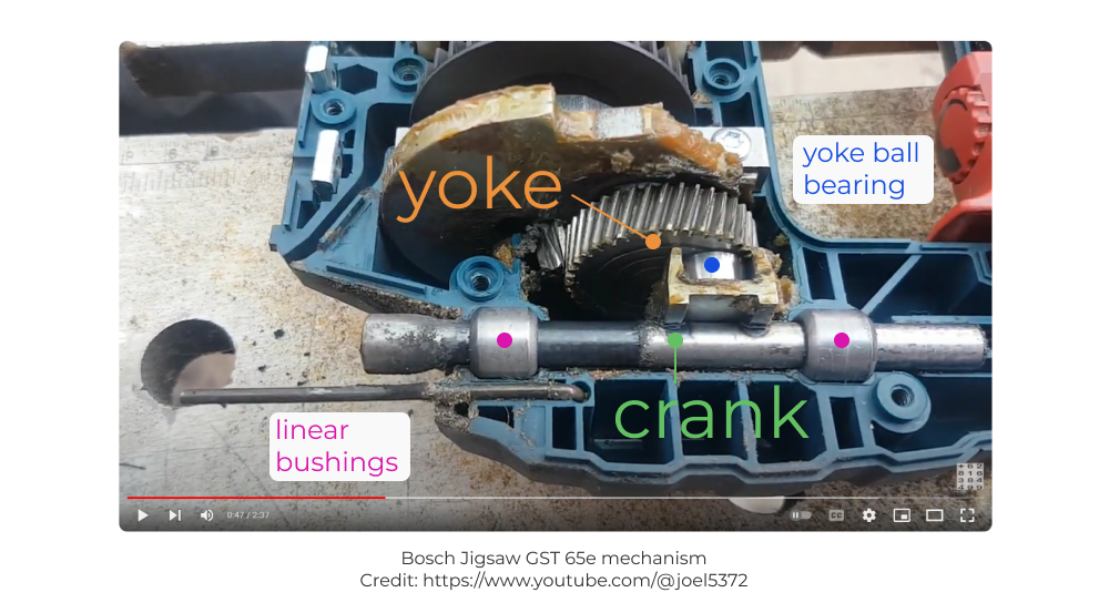
Note the clever usage of a helical gear as the crank, with a bearing mounted directly to the face of this gear, interfacing with a welded channel on the yoke slider (which holds the saw blade on one end). This is a simple and elegant solution that requires little to no service over its anticipated lifespan and allows for extremely compact packaging between the driveline and the blade yoke, thereby allowing the handle to be located near the blade.
An elegant Scotch Yoke mechanism is also used in Rotork fluid power actuators. In this case, only a portion of the stroke is used to actuate the mechanism allowing the yoke to backdrive the crank, which in turn rotates a valve open or closed.
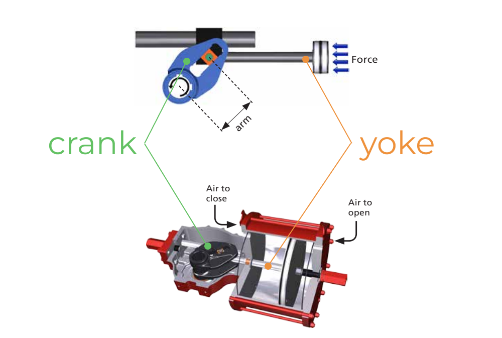
Scotch Yoke mechanisms are also employed in the design of various compressors and pumps (particularly diaphragm check valve pumps) along with some internal combustion engines.
Pros and Cons of Scotch Yoke Mechanism
Advantages
- Compactness: Its compact design is advantageous in space-constrained applications.
- Smooth Output Motion: The mechanism ensures a continuous acceleration and velocity profiles which help to minimize jerk and inertial loading.
- Simplicity and Reliability: Fewer moving parts mean easier manufacturing and maintenance, and often greater reliability.
Disadvantages
- Side Forces: Depending on the exact mechanical layout, the yoke can experience significant lateral forces and moment loads, which can lead to increased wear and tear. Additionally, the crank-yoke interface wear and friction must be managed carefully.
- Limited Stroke Length: The stroke length is inherently limited by the crank’s diameter.
- Variable Torque Requirements: The torque requirement varies throughout the rotation, which can impact the overall efficiency. This leads to a coupling between position and output force that must be considered during design, as contrasted with a linear pneumatic actuator which provides a more consistent force along the entire stroke length.
Conclusion
The Scotch Yoke mechanism is an elegant and simple mechanism that should be in every engineer’s design playbook. Converting rotary motion to linear motion (and vice versa) is such a common machine design pattern that it’s very beneficial to have Scotch Yoke mechanism design experience for these applications. By understanding the fundamental principles, geometrical configurations, and practical applications outlined in this article, experienced mechanical engineers can skillfully integrate the Scotch Yoke mechanism into electromechanical assemblies. Whether designing a jigsaw, an actuator, or a unique custom application, the insights and considerations discussed here, combined with the included excel worksheet should provide a solid foundation for designing your next Scotch Yoke mechanism.
Thanks for reading!
Bonus: 3D printable example mechanism
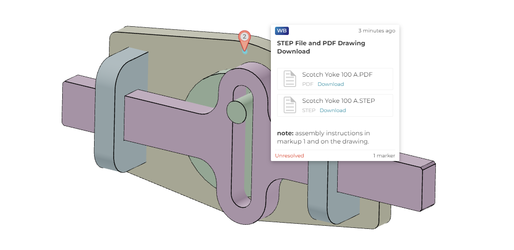
We designed a neat little 3d printable Scotch Yoke mechanism. Here’s an annotated Five Flute model that shows off the mechanism and includes CAD download links (STEP file) and a PDF assembly drawing if you want to print and assemble one yourself!
