Intro
Hi enginerds! This is the second article in a series of reverse engineering and teardown focused articles that we’re doing in 2024. These will not be your typical teardown blog posts. The goal with this series is to do some reverse engineering on popular products that have interesting mechanisms and design constraints that we can learn from. The focus will be on product engineering, design for manufacturability, analysis tools & techniques, and how you (dear readers!) can incorporate any discoveries and lessons learned into your own product development practice.
If you have a product you’d like us to reverse engineer and teardown, send a request to support@fiveflute.com and we’ll add it to our list!
Engineering Teardown
Product overview
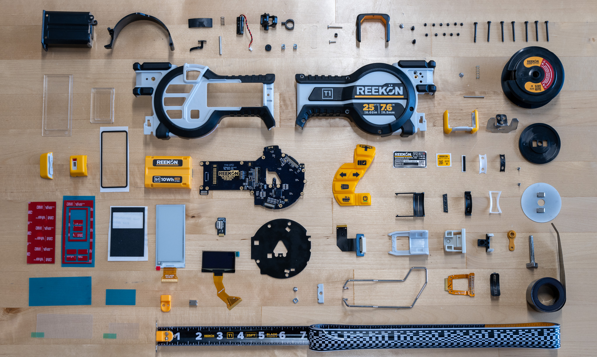
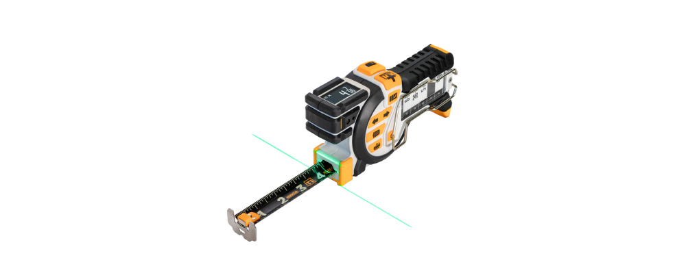
The REEKON T1 Tomahawk is a brand new entrant on the construction tools scene that in my opinion represents the future of smart tools. It’s a tape measure that includes some pretty interesting features like measurement saving (with a companion app), an e-ink display, integrated laser for measuring offset bodies, and some interesting construction details. As a new company, REEKON is hitting the ground running, but I’m always looking to find the warts and design lessons in a first generation product. So let’s dive into the overall architecture to understand how this next generation tape measure actually works.
Architecture & teardown
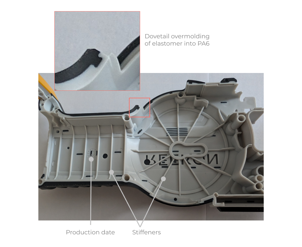
Like most power tools, the Tomahawk uses a two piece clampshell style construction with overmolded plastic. The clamshell material is PA6 with 30% glass fiber reenforcement. The overmolding is a thermoplastic elastomer labeled TPE-65A. Presumably that means thermoplastic elastomer with a shore A hardness of 65. At first I thought this was a different material than the TPS-SEBS overmolding from our Ryobi jigsaw teardown, but after finding this datasheet it looks to me like this is similar (if not identical) to TPS-SEBS but engineered for thin wall thicknesses. SEBS based thermoplastic elastomers are great for UV and heat resistance (siting out on a jobsite), but over time they really suffer if exposed to organic solvents.
PA6-GF30 is a great (and common) material choice for power tools and construction equipment. It’s very dimensionally stable, it has great strength and fracture toughness, and it has good enough stiffness to locate rotating componenents (like motors or encoders) very precisely and with minimal compliance.
Looking at the Tomahawk, one of the first things I worry about is the tape measure being dropped from a second or third story roof during usage. It’s quite a bit heavier than a basic tape measure and I hope the team designed for more than a 1m drop condition. That said, the housing looks burly as hell and it feels stiff in the hand. The overmolded thermoplastic is placed in the right locations to cushion falls in most orientations. I do however, worry that the LCD screen that displays the current measurement is not recessed enough to protect it from even a short fall onto gravel or jagged concrete edges. This type of scenario is extremely difficult to design for as an engineer because its almost impossible to sit down and write out a clear and useful set of requirements that covers 100% of actual use cases. I’m curious to see how REEKON iterates on this design once they have some feedback from experienced users and customer support data.
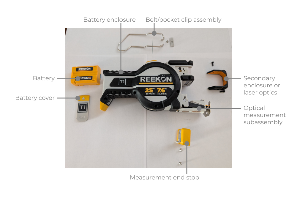
Before disassembling the main clamshell, you have to remove several subassemblies. The measurement end stop holds a very interesting optical measurement subassembly and serves as the butt end of the tape measure when in use. This end stop has to be aligned precisely with the green laser that shines down from the extension of the clamshell that houses the laser and laser adjustment/calibration components.
Internals and major subassemblies
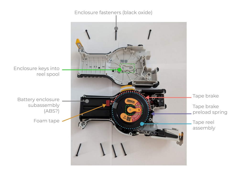
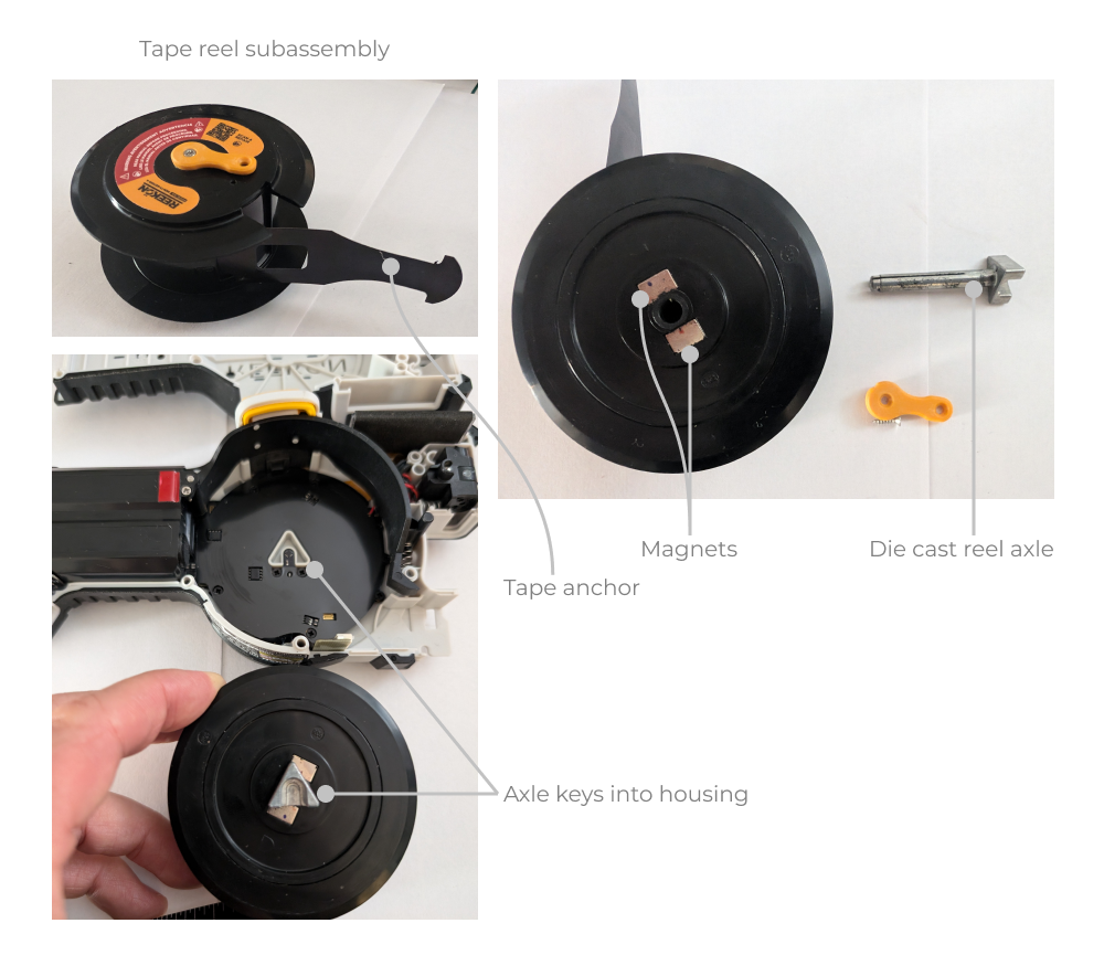
When you first crack into the enclosure, immediately you’ll see some interesting mechanical complexity. There is a central tape reel subassembly that is clocked into a recessed portion of the enclosure. Around the reel there is a spring preloaded brake pad (much like a drum brake in a car) that is connected to an external release button. The battery has it’s own (ABS?) subassembly that serves as the hinge for the brake pad. There is a small piece of plastic covered adhesive backed foam tape that preloads the battery enclosure subassembly against the top half of the primary enclosure. I can’t tell for sure, but this looks like a bit of a patch that was applied to the design during the later stages of development or the early part of the NPI process. Sometimes a simple piece of foam is the most elegant solution to remove rattlespace and make the assembly feel better. So far I’m impressed by the engineering in this first gen product.
Mold details
Overall the mold quality looks very high. There are no obvious grinding or rework marks on the core side of the mold or the ejector pins. The overmolding is keyed into the PA6 nicely with positive lock using through holes and dovetail features (highlighted below). This is all pretty standard stuff in the powertools game but its nice to see it included here.
Design for repair and replacement
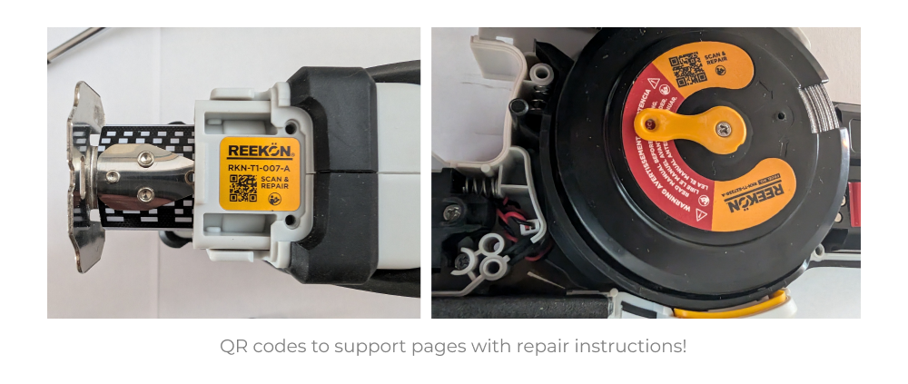
One of the most thoughtful touches in this product is the inclusion of QR codes directly on subassemblies that link to replacement and repair instructions. This is such a thoughtful touch by the REEKON team and I absolutely love it!
Reel assembly design
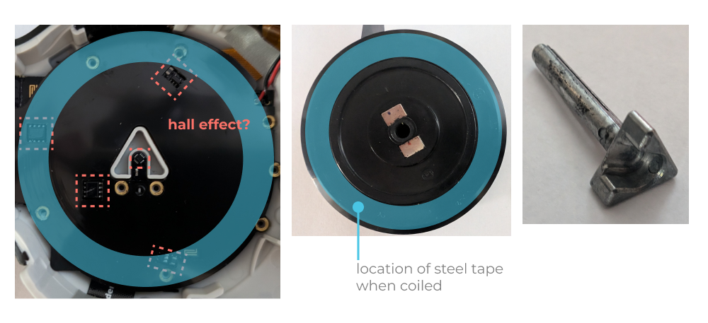
The tape reel assembly consists of a plastic hub (it feels like ABS), that looks ultrasonically welded or glued together. Inside it is a spiral watch spring that aids in tape retraction. A die cast axle connects to the watch spring. This axle is keyed into the enclosure to anchor the watch spring inner diameter.
Laser subassembly
The Tomahawk uses a laser projected at the zero line of the tape measure to allow users to visualize the projected plane of the tape measure origin. I’m guessing they use an off the shelf laser with integrated lensing that columnates the output. The core design problem here is how to align this module within the enclosure. The REEKON team has a pretty clever solution to use springs to preload the module against hard stops inside a housing. That housing is captured between the clamshell. It looks to me that there is a spring loaded clamp around the diameter of the laser that allows it to be positioned during calibration. Then once the final position is set, a dab of expoxy is used to lock in the laser assembly relative to the housing. Keep in mind I’m just taking an educated guess here, but at the very least there is some method of adjustment for calibration and then a method for permanently fixing components in their final location. It also looks like the screws may allow some adjustment or recalibration by users in the field.
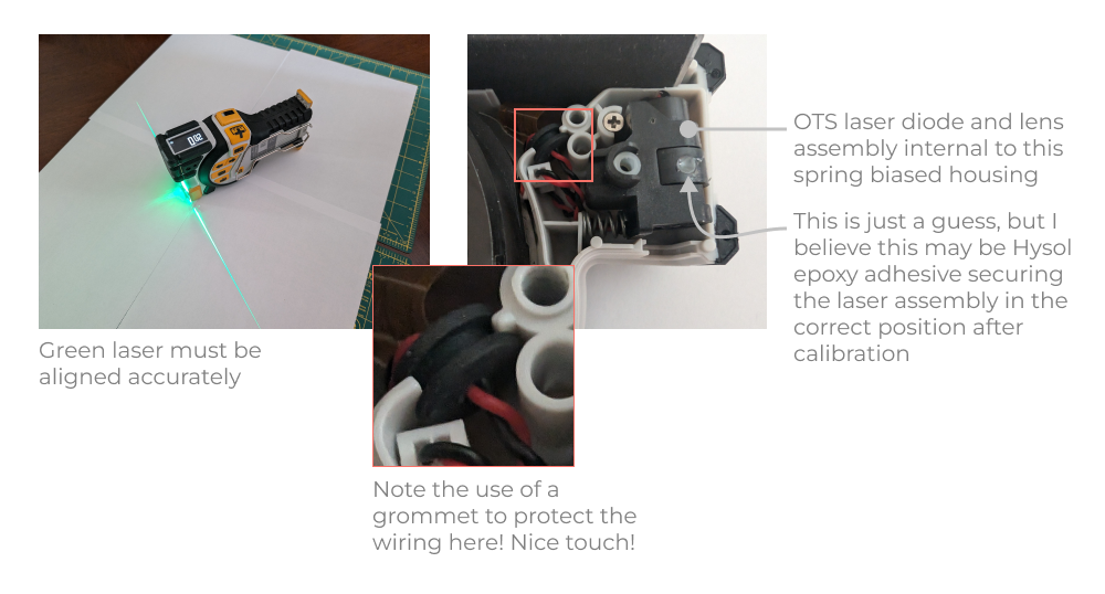
One very nice touch is the use of a grommet to protect the wire heading back from the laser module to the main PCB. This is the exact kind of detail we did not see on the Ryobi teardown.
PCB - the real hero of the Tomahawk design
Beneath the reel and battery subassemblies is a very creative piece of electromechanical engineering, the main PCB assembly.
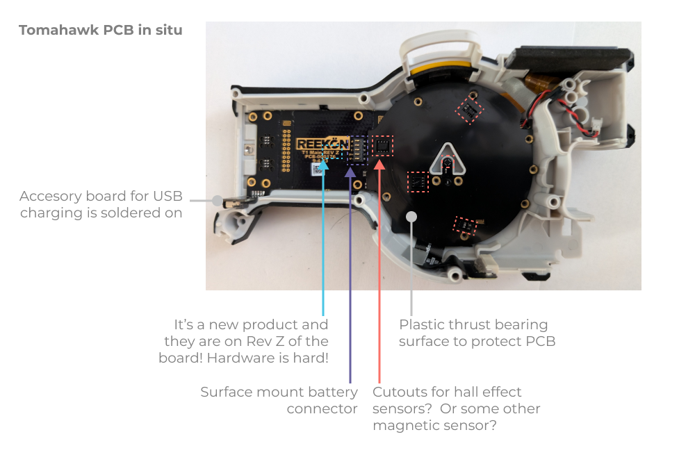
The PCB is covered by an adhesive backed thrust bearing surface that protects the PCB from contact with the tape reel. The bearing material looks a bit like 3M VHB with a low friction delrin, uhmw, or mylar sheet on one side. Note that in the image above, there a cutouts for surface mount components to stick out and sit close to the tape reel. I suspect most of those sensors are hall effect sensors of some type given the location of magnets on the tape reel and the proximity of the outer sensors to the measuring tape itself (as coiled on the spool). We’ll get more into that in the next section when we try to figure out how it all works!
Reverse engineering the measurement system
REEKON’s primary feature is it’s ability to display and log measurements. It’s a smart tape measure that allows you to push measurements to a companion application and to save them on the integrated e-ink display. I found the e-ink display to be very useful when measuring packing boxes and available space in a Pod during a recent move. It saved me from going back and forth between the Pod and various pieces of furniture and boxes inside.
In order to display the current measurement (amount of tape extended), the Tomahawk has to have a method for measuring the position of the tape. It looks to me like this job is done by an array of both magnetic and optical sensors. Let’s get into how I think they work.
Magnetic sensors
The array of magnetic sensors are located in interesting positions. Most notably, they are located across a range of diameters that both interact with the magnets on the tape reel, and interact with the coiled measuring tape itself. I suspect that the central magnets are part of an incremental encoder and the outer magnets are used to approximate the amount of tape coiled on the reel.
Optical sensors
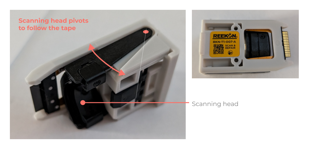
The REEKON team essentially engineered a small bar code reader into the Tomahawk. It’s actually quite an elegant electromechanical assembly. There is a code reading head that is allowed to pivot in order to follow the tape closely.
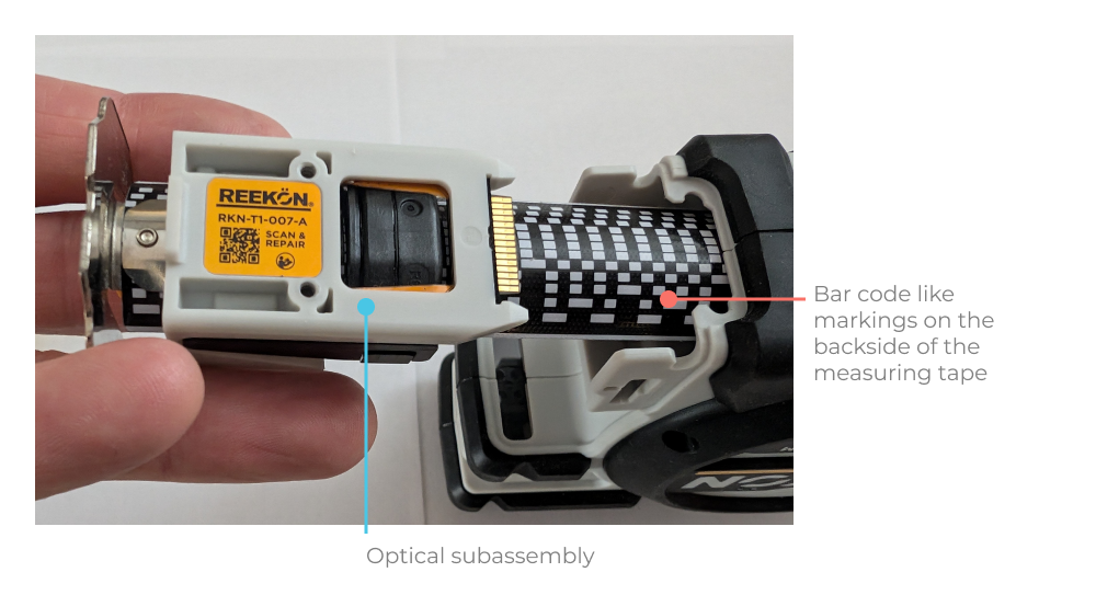
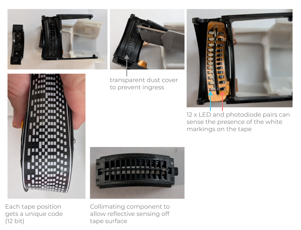
The scanning head contains an array of 12 LED and photodiode pairs on a flex circuit. There is a collimating cover that shields the LED output from the photodiode to prevent false positives. I’m guessing this allows the device to sense the presence of reflected LED light on the white portions of the tape. This effectively creates a 12 bit “bar code” system with a total of 4096 unique combinations. Each row is around 3mm long, so that yields up to 12,288mm or 40.31 feet of measuring tape without repeating patterns
Interestingly, on the front of the clamshell there is a stated measurement tolerance of ±0.020. This is smaller than the width of each unique bar code section so there must be some additional interpolation going on. My guess is there is some integrated look up table that linearly interpolates between bar code positions based on the magnetic sensor readings and an algorithm that considers the spiral winding of the tape and the associated change in diameter. I’d love to talk with the design team and understand exactly how they did it!
Implications of design complexity
Overall I really like the engineering behind the Tomahawk. I think it is a thoughtfully designed device with some real care put into its development. Building an encoder that is accurate to ±1/2 millimeter across a huge range of spooled up steel sheet is no joke. I think the engineering approach makes sense but I do worry about reliability given the number of sensors involved in measurement. Imagine if every sensor on the board had a (linearly independent) 0.27% chance of either malfunctioning or reading incorrectly due to dust ingress or damage every year (3 sigma reliability = 99.73%) . With 17 sensors involved in measurement (12 optical & 5 magnetic?) and if each sensor is critical to the measurement functionality, then there is a 4.5% device failure rate annually. This may not be conservative analysis at all, and my assessment of the single point failure behavior may be wrong, but it’s a bit scary to me!
All that said, I honestly don’t know how I would design this thing any differently than the bar code scanning approach.
Lessons learned and design tips
I wanted to highlight a few additional thoughts on the design that you can learn from and apply to your projects.
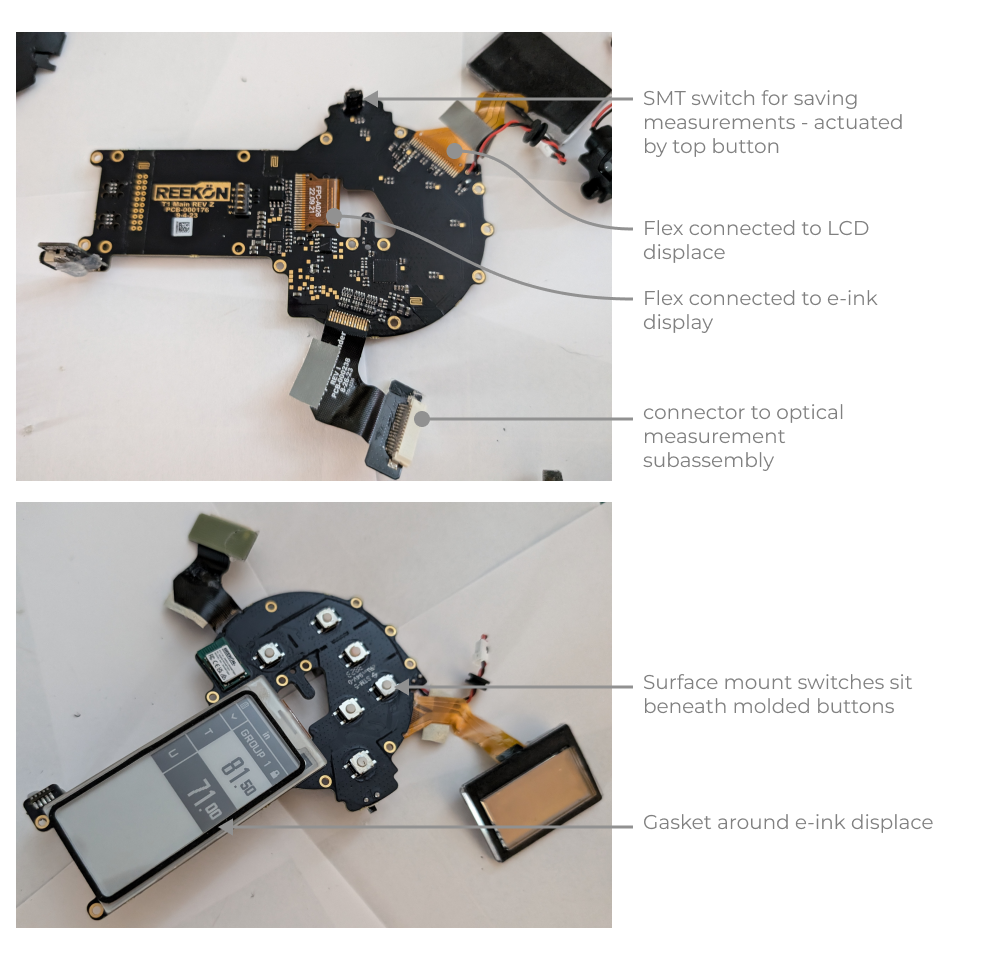
- I absolutely love the way the PCB is combined with flex and peripheral boards to allow a very ‘3D’ set of features to be assembled from a 2D manufacturing process. Super elegant. This design concept translates very well to all consumer electronics and you see it repeated elsewhere (Playstation controllers are a great example of using flex circuits to the max). This is a great technique to borrow in your designs.
- Unlike the Ryobi jigsaw we wrote about in our last teardown, the REEKON team did a great job managing the wiring of peripherals thoughout the clamshell. The inclusing of a little rubber grommet might not seem that important, but in a construction environment that could be a crucial design decision to increase reliability. Flex circuits and ribbon cables were routed intelligently and retaine with tape.
- Complexity always has a cost and it needs to be considered. Remember that failure rates can appear low on a per component level, but that can lead to an overall device performance that is not ideal. I’m obviously speculating here with regard to the Tomahawk, but its a good design heuristic to keep in mind. This translates directly to serialized manufacturing environements as well, where the cost of any manufacturing failure at a single station can shut down the entire line.
- Design for repair and replacement is just awesome! I love that the REEKON engineers included QR codes to support docs on key subassemblies. Super thoughtful.
Thanks for reading this one, what should we tear down next? Feel free to write us at support@fiveflute.com and let us know. Good luck with your hardware projects!
Related
How to Design a Scotch Yoke Mechanism