Engineer's Guide to Lightweight Part Design
Why Lightweight Parts?
In the pursuit of superior performance across various industries, lightweight parts have become a cornerstone of engineering and design. Whether in bicycles, rockets, satellites, cars, boats, or planes, reducing weight translates to enhanced structural efficiency and overall performance. In each of these applications, lighter components contribute to better fuel efficiency, improved handling, and increased speed, making lightweight design an essential skill for the modern design engineer. Plus it’s one of the most fun engineering optimization challenges you will ever encounter. The constraint space of maximizing stiffness or strength while also minimizing weight is such a delightful and common challenge that its worth diving into, so that’s what we’ll be focusing on in this article. If you work in aerospace, vehicle design, renewable energy, or any other industry with structural efficiency driven performance, this article is for you!
How to Design Lightweight Parts
Requirements: Strength Driven or Stiffness Driven
As with any other engineering problem, its always a good plan to start by thinking through the driving design requirements. In the case of lightweight parts, I find it immensely helpful to understand if the design in question is stiffness driven or strength driven.
- Stiffness driven design: Stiffness driven applications require a given amount of compliance in order for the part to be performant. Usually they involve minimizing deflection under expected loads, or just maximizing flexural modulus, modal/vibration responses, or other stiffness metrics.
- Strength driven design: Strength driven applications require components to withstand loading conditions (without failure) primarily, and generally can tolerate a range of component displacements while still being performant.
Identifying this requirement early in the design process helps in selecting appropriate materials and design techniques.
Note: In some instances, manufacturing processes limit the design. For example, for vibration reasons, the wall thickness of a CNC machine part may be thinner than is actually manufacturable. In these instances, DFM optimization is more important than strength or stiffness optimization.
Materials Selection
Usually the material choice in light weight applications is a balance between cost, manufacturing method, strength, and stiffness. In aerospace applications, common metals include aluminum alloys, titanium, stainless and high strength steels, Inconel, Hastelloy (and other nickel based alloys), and magnesium. In addition to metals, composites play a large role in modern light weight designs - this includes carbon fiber reinforced plastics, glass fiber, and Kevlar. With so many options, it can be hard to evaluate the tradeoffs and make a good material choice.
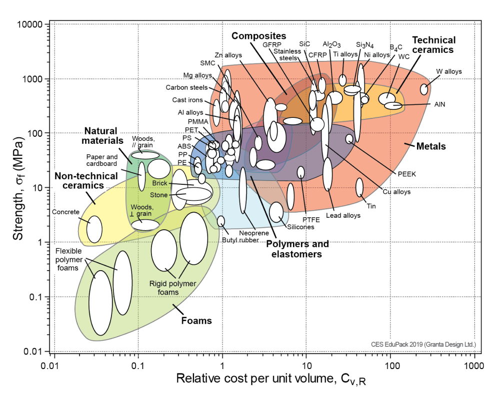
Ashby Charts
That’s where Ashby charts come in handy! Ashby charts are a valuable tool for material selection in lightweight design. These charts plot material properties, such as density, strength, and modulus, against normalized cost (or other parameters), allowing designers to compare and choose materials that best meet their performance criteria. They are a fantastic way to visualize a broad trade space and zero in on candidate materials to explore further.
Techniques for Designing Lightweight but Stiff Parts
Optimization
Effective lightweight design involves strategically placing material where it matters most. By definition this means lightweight part design involves some amount of optimization of part performance per unit mass. Oftentimes this is described as a maximization of (mass) specific stiffness or specific strength. There are a number of optimization methods that matter for lightweight part design. Here are the various methods, along with some thoughts about the utility of each approach and when to use them.
-
Design by first principles guided intuition. It sounds hilariously non-analytical, but a moderate understanding of tensile, bending, and shear stress flows through a part will allow you to intuit where the mass in your parts should be. Often this is enough to arrive at the basic architecture of a design. Pro Tip: I like to tune my design/stress flow intuition by sketching over part designs how I think stress will flow and then checking that against my FEA results.
-
Hand calculations. The next step in optimization typically involves some kind of hand calc or set of hand calcs to arrive at a more refined geometry (wall thickness, beam profiles, bolt sizing, contact area, material choices etc…). Roarks Formulas for Stress and Strain is a great reference text for this kind of work! Believe it or not, there are probably lots of parts on the Falcon 9 or other spacecraft that are designed entirely with simple hand calcs and then qualified on vibration rigs and vacuum chambers. Even in projects with extremely high cost per kilogram, engineers don’t have time to chase down every single gram. Progress must be made rapidly and hand calcs are a crucial methodology for any design engineer.
-
FEA. Commercial finite element solvers are baked into CAD these days and running a static analysis on a simple part can take less than 10 minutes in many cases. With a bit of iteration and convergence checking, you can get FEA results that are in line with your hand calcs in about an hour.

-
Topology Optimization. Topology optimization is a computational technique that helps designers identify the optimal material distribution within a given design space, subject to specified constraints. This method often results in organic, complex shapes that are both lightweight and strong. You can think of topology optimization as a set of geometry modification algorithms wrapping a finite element model. Because of how powerful this method is in lightweight part design, and its relative complexity, we’re going to dive deeper into how it works.
How Topology Optimization Works - Process Overview
Topology optimization involves a few relatively standard steps. (We won’t be referencing any particular design software, instead we’ll focus on generic steps you can apply in any software)
- Create some initial geometry. This initial geometry should define the bounds of the part (some folks call this a space-claim). Effectively you’re giving the optimization routine a set of geometric boundaries within which it is free to modify the part by adding and removing material. This is particularly valuable in tight aerospace packaging environments where you have keep out zones established by neighboring parts and assemblies.
- Establish invariant geometry. You’ll need to explicitly tell the topology optimization tool what part geometry must be present.
- Apply boundary conditions. For topology optimization to work, you’ll need to apply the complete range of expected loading and constraint conditions that you expect the part to experience in usage. This is incredibly powerful and also super dangerous! It’s quite easy for human beings to miss or leave out critical loading cases because they are not well understood. This means you may have a part that is optimized for a handful of cases, but this optimization process then causes the part to fail under other more benign (yet unspecified) load cases. Use caution at this step and be super thorough or you’ll end up with some gnarly failures!
- Choose what to optimize. Topology optimization software needs to understand what it is optimizing - strength, stiffness, heat transfer, etc. The magic of the approach is that it will find a global optimum across a broad range of boundary conditions, satisfying all of them according to your optimization parameters (gradient descent for the win!)
- Evaluate the results. Just like any other analysis method, the results need to be trustworthy. Topology optimization should always involve an evaluation and tuning phase to make sure the results are believable and robust.
- Export geometry. Finally, the geometry needs to be brought back to CAD for final tweaks.
- DFM tweaks. Topology optimized geometry is often easy to 3D print, but can be impossible to manufacture via other methods (CNC, casting, extrusion etc..). The final step in this process is to ensure that the finished design is manufacturable by the desired process.
Design Patterns to Know - Beams, Webs, Ribs, Isogrids, and Other Structures
Geometries such as beams, webs, ribs, and isogrids help distribute loads efficiently while minimizing weight. CAD tools like nTop enable the creation of conformal ribbing and lattices, and other geometries that enhance structural integrity and heat transfer properties. Lets take a look at these common design patterns so we can start to build our recipe book for lightweight part design.
Beams. Beams are a foundational element in machine design, so understanding the relationship between a beam’s cross sectional geometry and it’s flexural modulus is essential for designers to understand. This is the foundation of lightweight part design. Looking back into your mechanics textbook, make sure you familiarize yourself with the concept of second area moment of inertia, and how it scales as a function of beam geometry.

Torsion tubes. For structures that undergo combined bending and torsion, its essential to understand which loading case dictates the geometry, and how the relationship between bending stiffness and torsional stiffness can be competing at times. Think about how mass efficient an I-beam is in bending and then how torsionally compliant it still is. This kind of tradeoff is difficult to intuit across a broader range of cross sectional geometries and loading conditions. (But that’s why engineering is fun, right!?). From both an intuitive and analytical perspective, you’ll want to be familiar with what drive’s polar area moment of inertia.

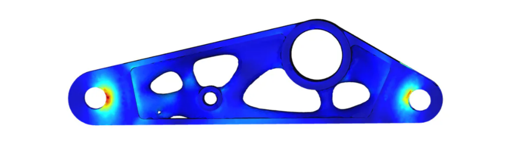
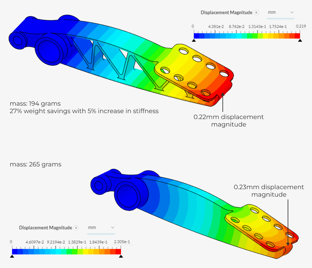
Webs and ribs and triangulation. Webs and ribs are the most used lightweight design technique for CNC machined and cast aerospace parts. If there is one single area to master in lightweight part design, especially for aerospace applications, it would be the judicious usage of webs and ribs to manipulate and optimize part strength, stiffness, and vibration performance.
Here’s an example part to demonstrate how much mass you can save while preserving stiffness.
Tesla has done an outstanding job of DFA and DFM by designing integrally stiffened large (giga)castings for the front an rear sections of the vehicle.
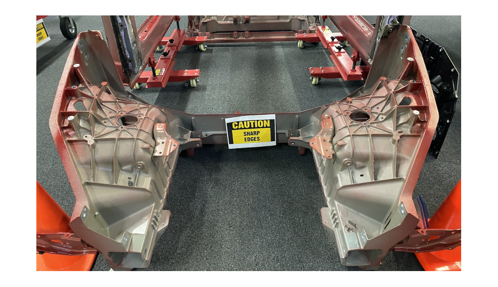
These structures are insanely stiff because of the section properties they achieve. The castings are handling enormous bending loads where the vehicle shock towers are structurally anchored. They are able to withstand this loading with wall thicknesses in the range of 3mm or less, precisely because the web properties and triangulation result in efficient flexural modulus and smooth stress flow across the assembly. It’s really a thing of beauty in my opinion!
Isogrids. My favorite example of an isogrid design is the Boeing Starliner pressure vessel.
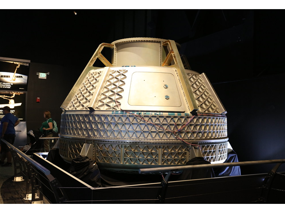
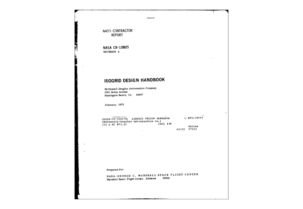
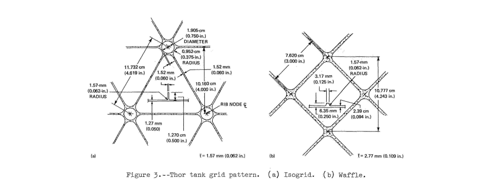
Isogrids are so efficient in cylindrical pressure vessel applications (capsules and domed tanks for example), that NASA has an Isogrid Design Handbook from the 1970s! They were first studied by Dr. Robert R. Meyer under NASA contract in 1964.
The real magic of the isogrid design, and the reason it is called an isogrid is that isogrids behave like an isotropic material of an equivalent thickness. This makes them very easy to understand and design, which was super handy in an era of limited compute and applications with high consequence for structural failures.
I’d recommend you skim through this paper on the design and analysis of the delta rocket isogrid structures. It really gives you a sense for the structural importance of isogrids in spacecraft design. NASA put in a ton of effort analysing and characterizing these structures using very early versions of NASTRAN running on IBM 360 machines - extremely hardcore engineering in a limited compute era.
Pro Tip: nTop allows conformal isogrid structures to be wrapped around complex surfaces.
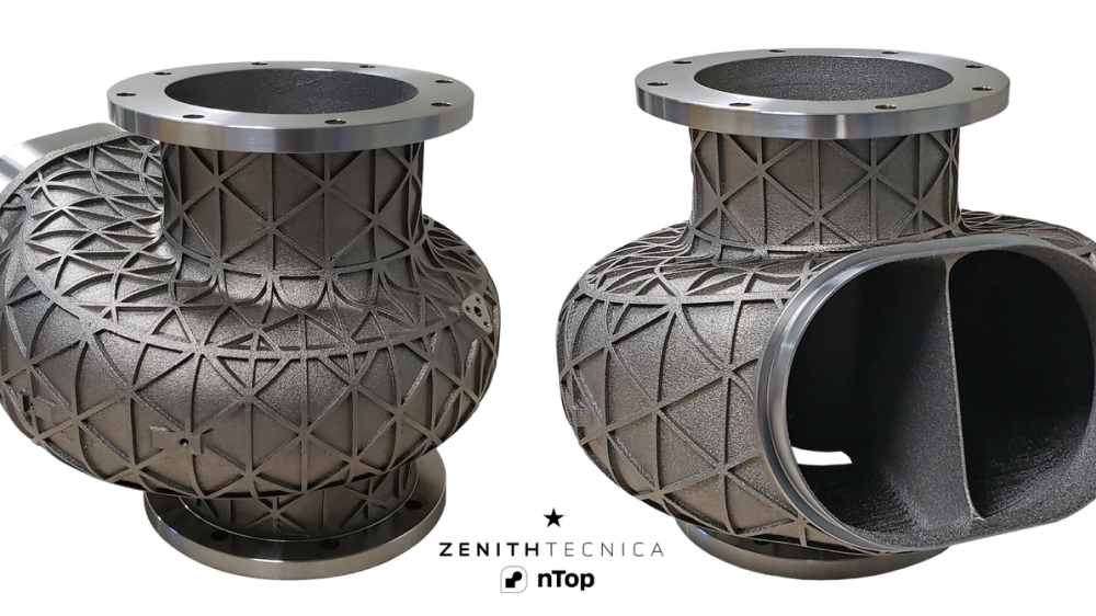
(image credits: nTop)
Composites
Composites have been pioneered by aerospace and automotive racing applications, but are now trickling down into other industries. There are a number of advantages from a structural efficiency standpoint that composite structures offer, including:
- High Strength-to-Weight Ratio: Composites like carbon fiber and fiberglass provide exceptional strength while being much lighter than traditional materials such as metals.
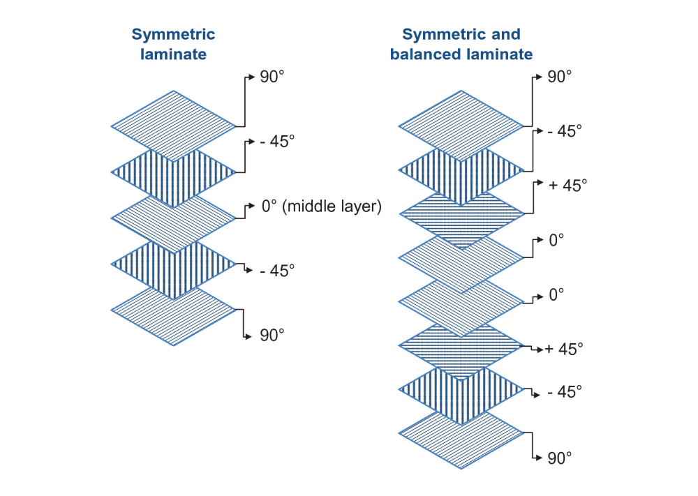
- Customizable Properties and Anisotropic Behavior: The properties of composites can be tailored by varying the orientation and types of fibers and resins used, allowing designers to optimize lightweight parts for specific strength, stiffness, and weight requirements. Additionally, designers can target quasi-isotropic performance with balanced and symmetric layups, or use asymmetries in layup geometry to tune component stiffness and strength. This allows designers not only to tune the stiffness, but also to control the deflection characteristics and mode shapes of a structure.
A great example of this kind of design is on aircraft wings. They can be tuned to prevent flutter at certain speeds, thereby enabling lower overall part mass through controlled stiffness.
-
Corrosion Resistance: Composites are highly resistant to corrosion and chemical damage, making them suitable for harsh environments where metals might degrade. From a lightweight design standpoint, this is an advantage inasmuch as it allows you to target a lower design factor of safety because the lifetime of wear will be more advantageous for a composite structure.
-
Durability and Fatigue: Composite materials generally have a longer lifespan and are less prone to fatigue and wear compared to traditional materials. Again this allows lower factors of safety and less redundant mass.
-
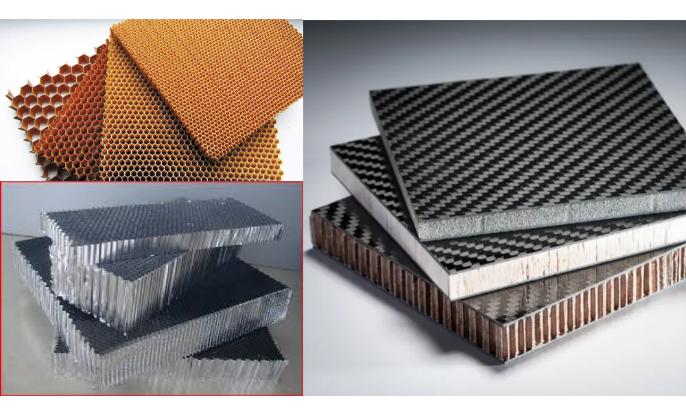
Design Flexibility and Sandwich Panels: Composites can be molded into complex shapes more easily than metals, allowing for innovative design solutions that would be difficult or impossible with traditional manufacturing methods. The molding process is particularly effective when combined with sandwich panel construction. Sandwich panels use a light weight material such as balsa, foam, or honeycomb panels of nomex or aluminum to space composite plies away from each other. This effectively creates a beamlike structure with properties not unlike an I-beam. The sandwiched material must transfer shear between the top and bottom skins. These skins take the bulk of the in plane stresses induced by bending and torsion.
-
Reduced Assembly Requirements: Due to the ability to mold complex shapes in a single piece, composites can reduce the number of parts and fasteners needed, simplifying assembly and reducing potential weak points. Part count reduction is perhaps the most effective design for assembly methodology, and simplifying assemblies by integrating multiple component functions into a single monolithic piece is a great way to reduce fastener count, structural redundancy, and save weight.
These advantages make composites a popular choice in industries such as aerospace, automotive, marine, and sporting goods, where reducing weight without compromising performance is crucial. Just be wary of the cost and complexity of composite designs, as well as the difficulty in adapting them when inevitable issues are discovered.
Important Manufacturing Methods for Lightweight Parts
CNC Machining
CNC machining allows for precise material removal, making it ideal for creating lightweight components with complex geometries. The most difficult part of lightweight CNC part design is mitigating part vibration and tool chatter during manufacturing. Thin walled ribs, flanges, and pocket floors can vibrate during cutting, causing resonant behavior, damage and tolerance issues. Check out our DFM for CNC article for the best practices and first principles that will guide your lightweight CNC designs.
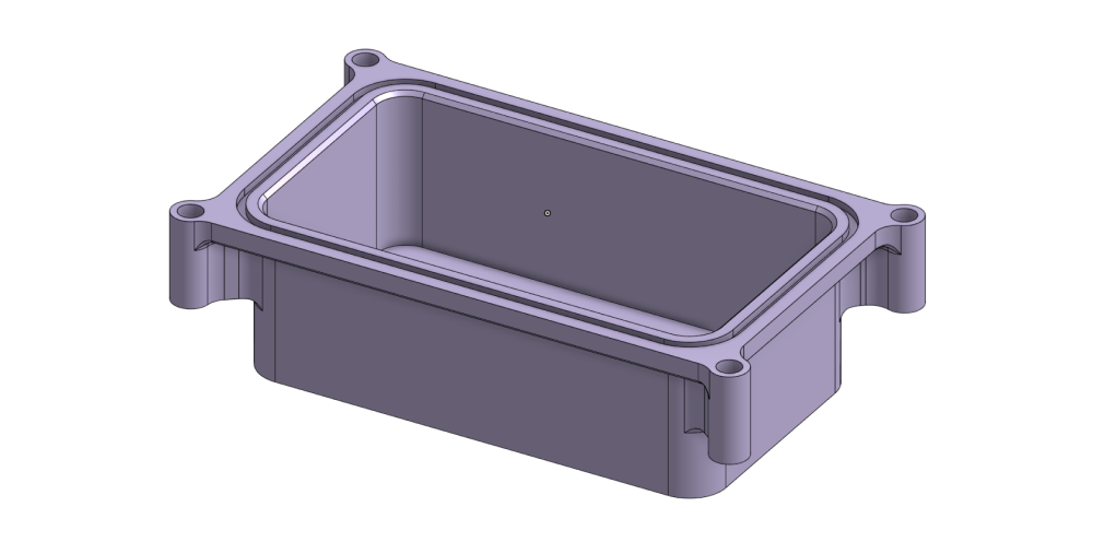
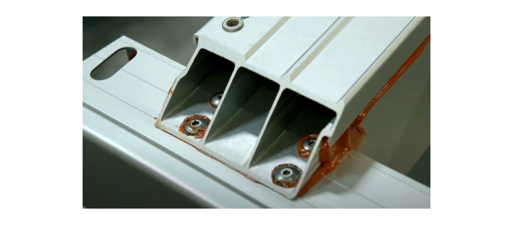
Take this with a complete grain of salt, but in aerospace applications, I’ve been able to design enclosures with wall thicknesses down to 0.050” in aluminums and 0.040” in steels and titaniums. Obviously this is highly geometry dependent, but a good machinist can come up with a fixturing strategy to get wall thickness well below 2mm.
Example Model: Here’s an example enclosure chassis design that is representative of what’s typical in aerospace.
3D Printing
3D printing technologies such as Direct Metal Laser Sintering (DMLS) and Stereolithography (SLA/SLS) enable the production of lightweight parts with intricate designs that would be difficult or impossible to achieve with traditional manufacturing methods. DMLS is fantastic for creating integral and conformal ribbing or lattice geometries designed with nTop (think heat exchangers and rocket engine nozzles and combustion chambers).
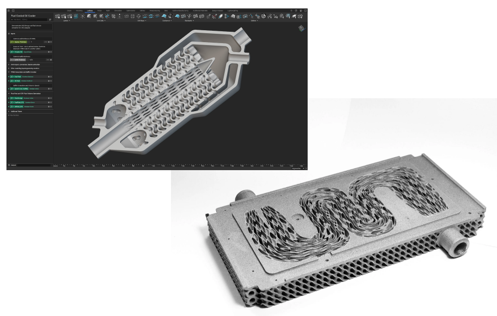
(image credits nTop)
Note: Recently the Space X Raptor 3 engine made the rounds online. It’s a fantastic example of design simplification, mass and complexity reducition, by using DMLS. Here’s the Raptor 3 engine compared to its predecessor designs.
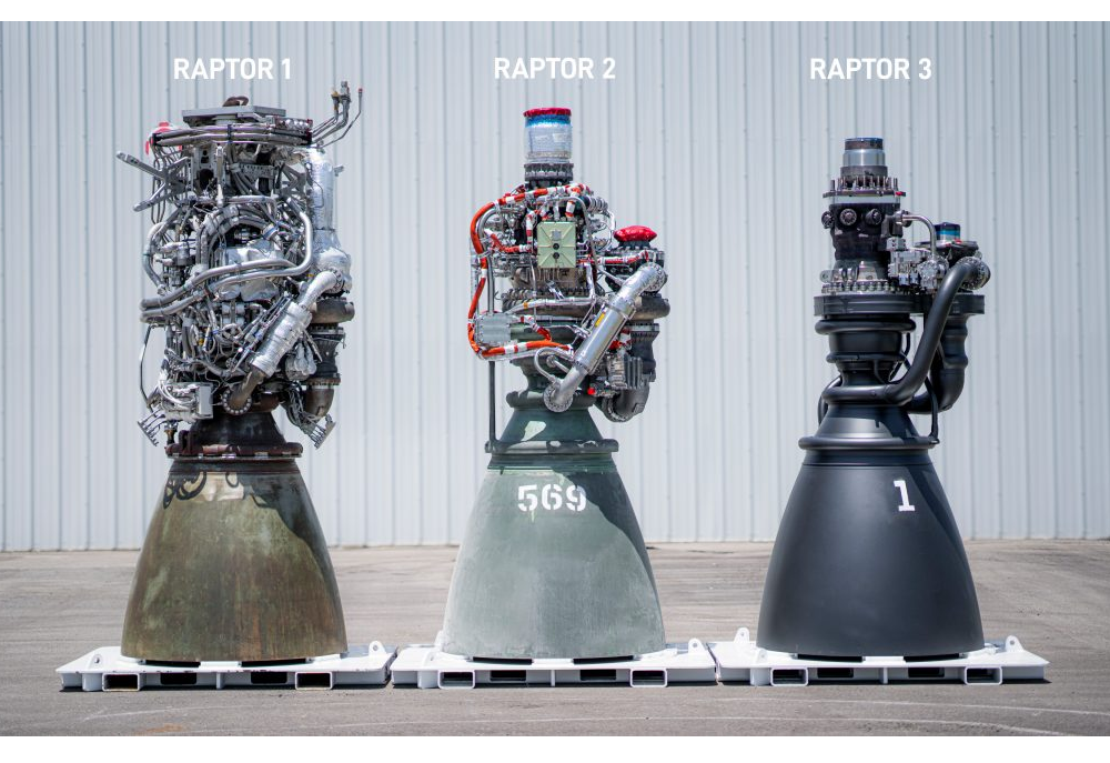
All of the tubing you see in Raptor 1 and 2 has been eliminated by moving geometry internal to 3D printed parts.
Sheet Metal
Sheet metal fabrication, including techniques like deep draw and hydroforming, is useful for creating lightweight parts with high strength-to-weight ratios. It is commonly used in the automotive and aerospace industries. This can be particularly effective when wall thicknesses dip below 1mm, or whatever can be readily CNC machined with reasonable fixturing techniques.

Friction Stir Welding
Friction stir welding reduces heat-affected zones, preserving the material properties of lightweight alloys. This method is particularly useful for joining lightweight materials without compromising their strength. You’ll see this technique employed on rocket tank joints and other large cylindrical aerospace assemblies.
Learn More: Astra has a great video on their friction stir welding setup.
CAD Modeling and Analysis of Lightweight Parts
CAD Modeling Methods for Lightweight Parts
CAD modeling lightweight parts can be a challenge. In general, the more lightwieght a part, the more intricate and detailed the geometry. This can lead to issues with CAD model robustness and difficulty improving or modifying the design as you continue to optimize it’s performance. Here are a few approaches to keep in mind if you are designing lightweight parts in a traditional CAD tool (not nTop).
Detailed Sketches, Offset geometry and triangulation
This is a bit time consuming, but it makes for reasonably robust models. I like to either create a single driving sketch that includes all rib and stiffening geometry if the part can be created with a handful of simple extrusions. Alternatively, you can create a driving sketch for any cutout geometry or other boolean operations. Here’s a quick racecar brake pedal example that I designed.
First I created a single sketch for the exterior 2D bulk geometry. Then I created the base extrusions. Then I created a single sketch for all cutout (pocket and truss) geometry. Note that this cutout sketch leverages offsets from existing geometry, which saves modeling time by reducing effort during sketch development.
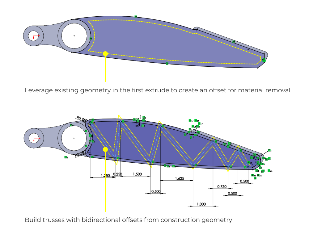
I also really like to use construction geometry for trusses, and then bilateral offsets (in SolidWorks) to create the truss web geometry. This gets detailed with a few fillets and some cleanup, and then the body is mirrored to make a symmetric part.
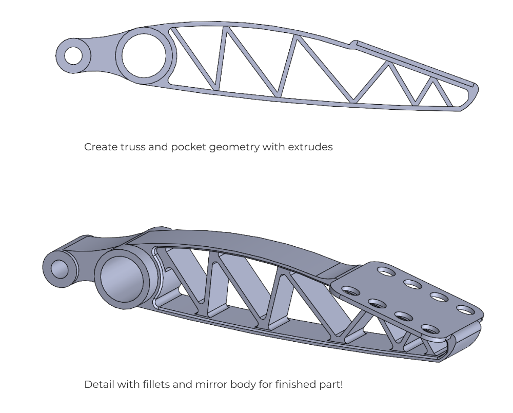
So in 15 minutes I have a design that is relatively parametrically flexible, easy to modify, and one that I can begin to analyze and optimize.
Shells
Shell methods are fantastic for plastic part design as well as lightweight castings. The feature tree order of operations with shell features and other details like ribs and and stiffeners can get a bit tricky. Just remember that the shell operation will make geometry that is offset from the outer surface, this means you need to figure out a way to CAD model all stiffeners and add on geometry (flanges and bosses etc…) after the shell operation. Otherwise you’ll end up with a brittle CAD model that is very hard to optimize.
CAE and Analysis of Lightweight Parts
The two biggest analysis concerns with lightweight parts are vibration and buckling. Usually, buckling instability is not a concern in most machine design components. The removal of part mass and the usage of thin sheet structures with complex geometry makes buckling a more likely failure mode that is also hard to intuit. Combine this with tricky vibration modes (drumhead, combined bending and torsion, etc..) and you’ve got a recipe for difficult analysis! From an FEA perspective, element choice becomes a crucial driver of model performance as wall thickness get small. Check out this article on FEA fundamentals to dive deeper.
On top of buckling and vibration, aerospace structures are subject to fatigue failure because of the cyclical nature of loading conditions associated with flight operations. Usually the extra mass baked into static factors of safety is enough to make fatigue a non-issue in most machine design parts, but that’s not the case with lightweight metal components, especially in aluminum!
Assembly Considerations
Principles of Lightweight Design
In an assembly, the best way to reduce mass is to get rid of things. It’s just that simple. Of course this is easier said than done, so let’s talk about how to reduce part count specifically.
The most effective method I’ve encountered is to design structures to be multi use. Think about the difference between a body on frame and unibody automotive designs. In Formula one, the engine and gearbox assemblies are a stressed portion of the chassis. They handle 100% of the torsional loads across the vehicle! Tesla takes advantage of this principle of dual usage by using their battery enclosures as extremely stiff structural elements of the chassis.
The key idea here is to combine the functionality of multiple collocated parts into more monolithic forms. This often comes at the cost of manufacturing and servicing the part, or assembly dependency complexity.
In addition to combining parts, look for creative ways to reduce fastener counts and/or eliminate welds. Lotus was able to combine adhesives with rivets to fasten and bond aluminum extrusions in their chassis manufacturing process. The beauty of this approach is that it allows custom optimized extrusion profiles to be used in the chassis. The bonding and riveting saves further wieght by eliminating welding. This elimination of welding allows all the constituent extrusions to be heat treated before assembly and to maintain adequite strength at lower wall thicknesses that would be used in a fully annealed metal (from the heat effected zone of a weld).
Mass Budgets and Optimization
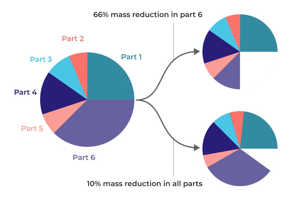
In large complex design projects like vehicles or rockets, it can be difficult to focus weight reduction efforts efficiently. This is where mass budgets come in. In general its a good practice to track the mass of every part and then to judiciously apply lightweight optimization efforts in areas that will yield the largest return per engineering hour or dollar.
In the example below, a 66% mass reduction in a single part is more effective than a 10% mass reduction in every part in the assembly. This is obviously a simplified example, but its likely that there are only a handful of significant areas for mass reduction in any system and you should be cognizant of where you spend your engineering effort.
I know all of this sounds obvious, but it is often a task that is ignored because no single engineer owns the integration aspects of the design, and instead the team functions as a collection of subspecialists with poorly aligned incentives. Mass reduction is a mechanical AND systems engineering problem in complex projects, so build a mass budget and work strategically to reduce it.
Closing Thoughts
Designing lightweight parts is crucial for improving performance across industries like aerospace and automotive. It’s a fun but intimidating design challenge that I hope you are better equipped to face after reading this article. On your next lightweight design, remember to think through the requirements (stiffness vs. strength-driven), select the right materials, and use an appropriate optimization method give your budget and level of effort. If you understand the first principles of CNC, casting, sheet metal, and composites manufacturing methods, you should be well equipped to design cost effective and functional lightweight parts. Finally, don’t forget to think through the systems implications of where you direct lightweighting effort. A mass budget can go along way to aligning the efforts of your design team.
Last but certainly not least, lightweight part design is RISKY! You’ll definitely want to share your designs with peers and capture feedback in design reviews. If you want to spend less time in powerpoint or sharing screenshots, and more time problem solving with other engineers, give Five Flute a try. I can give you a 15 minute demo and show you how it works. We’ll help you get back to the engineering that you love doing!